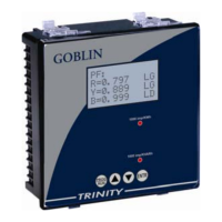
Goblin – Operational Manual
TRINITY
[9]
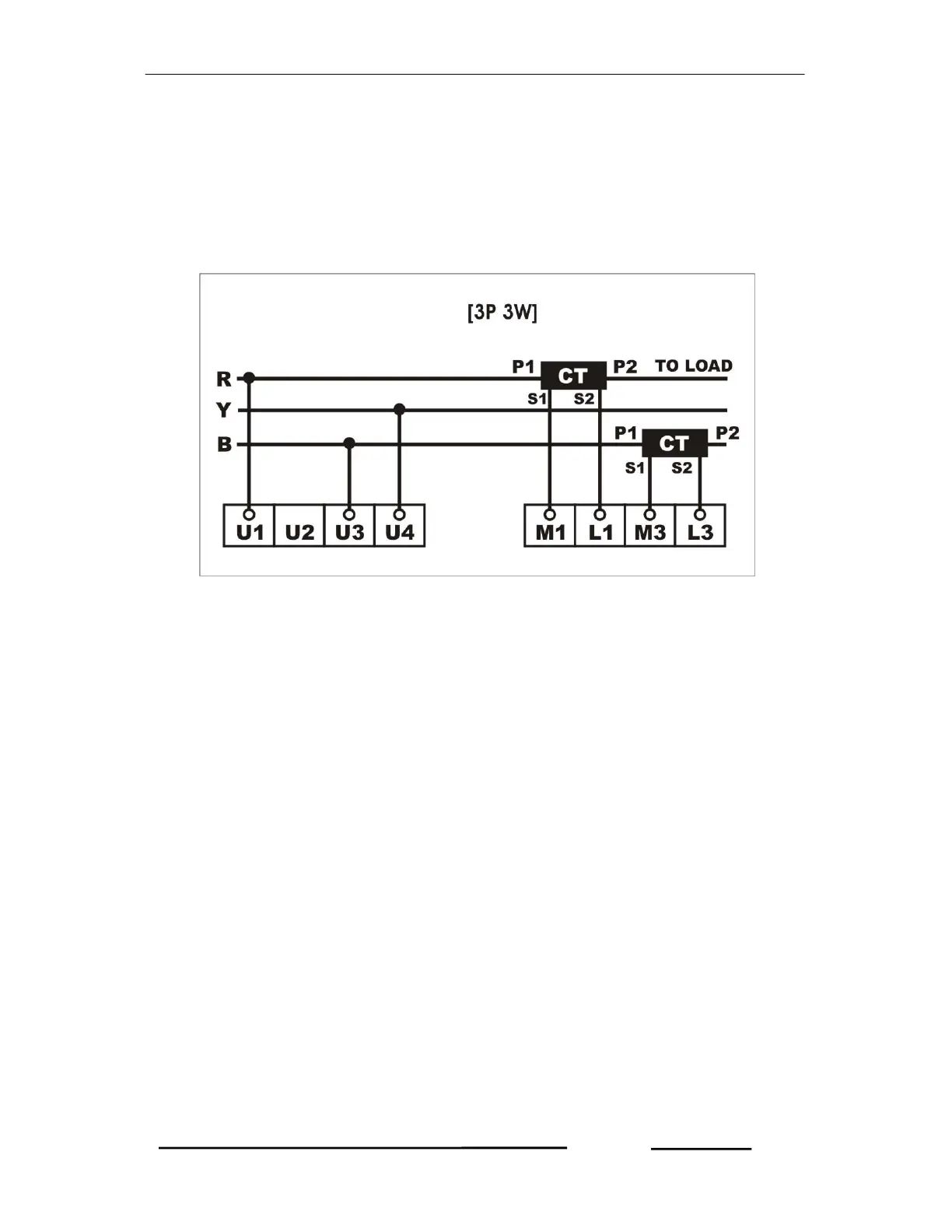
3P3W Mode Installation
Follow these steps to install / commission the unit.
1. Push the unit into the panel and mount using the clamps provided. Connect
the Auxiliary supply to the terminals marked P and N. The Auxiliary supply
range is 80 VAC to 270 VAC.
2. Connect the three phases with the R phase to the terminal U1, B phase to
terminal U3 and Y phase to terminal U4. Make sure that the three phases
coming to the unit come through control fuses of 1.0 amp rating. This will
protect the electronics inside from damage due to severe overvoltages or
phase faults in the system.
3. Connect the two wires from the R-phase CT to terminals marked M1 & L1
such that S1 from CT goes to M1 on the unit. Connect the two wires from the
B-phase CT to terminals marked M3 & L3 such that S1 from CT goes to M3
on the unit.
4. Switch on the three phase supply. The unit will come alive and display power
receiving information such as factory location for about three seconds and
then, it will display the first page of Run Mode.
5. If there is very little current or no current in the CT circuits, the unit may show
PFs as 0.999 or 1.000. This will go away as soon as the current builds up in
the CTs, above 0.4 % of rated CT.
6. Now, the unit needs to be programmed for the various parameters which are
field programmable. For this refer to next section “OPERATIONAL DETAILS”.
7. The unit is ready for operation.