EasyManuals Logo
Home>TSC>Printer>TTP-286MT Series

TSC TTP-286MT Series Service Manual

TSC TTP-286MT Series
39 pages
To Next Page IconTo Next Page
To Previous Page IconTo Previous Page
Page #25 background imageLoading...
Page #25 background image
23
23
3.9 Replacing the Gap and Black-mark Sensor Module
1. Open the printer right side cover.
2. Disengage printhead release lever.
3. Refer to section 3.1 and 3.4 to remove electronics cover and multi-interface board.
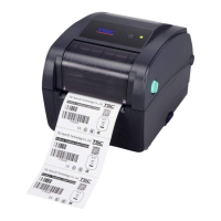
4. Disconnect the gap and black-mark sensor connectors from the main board.
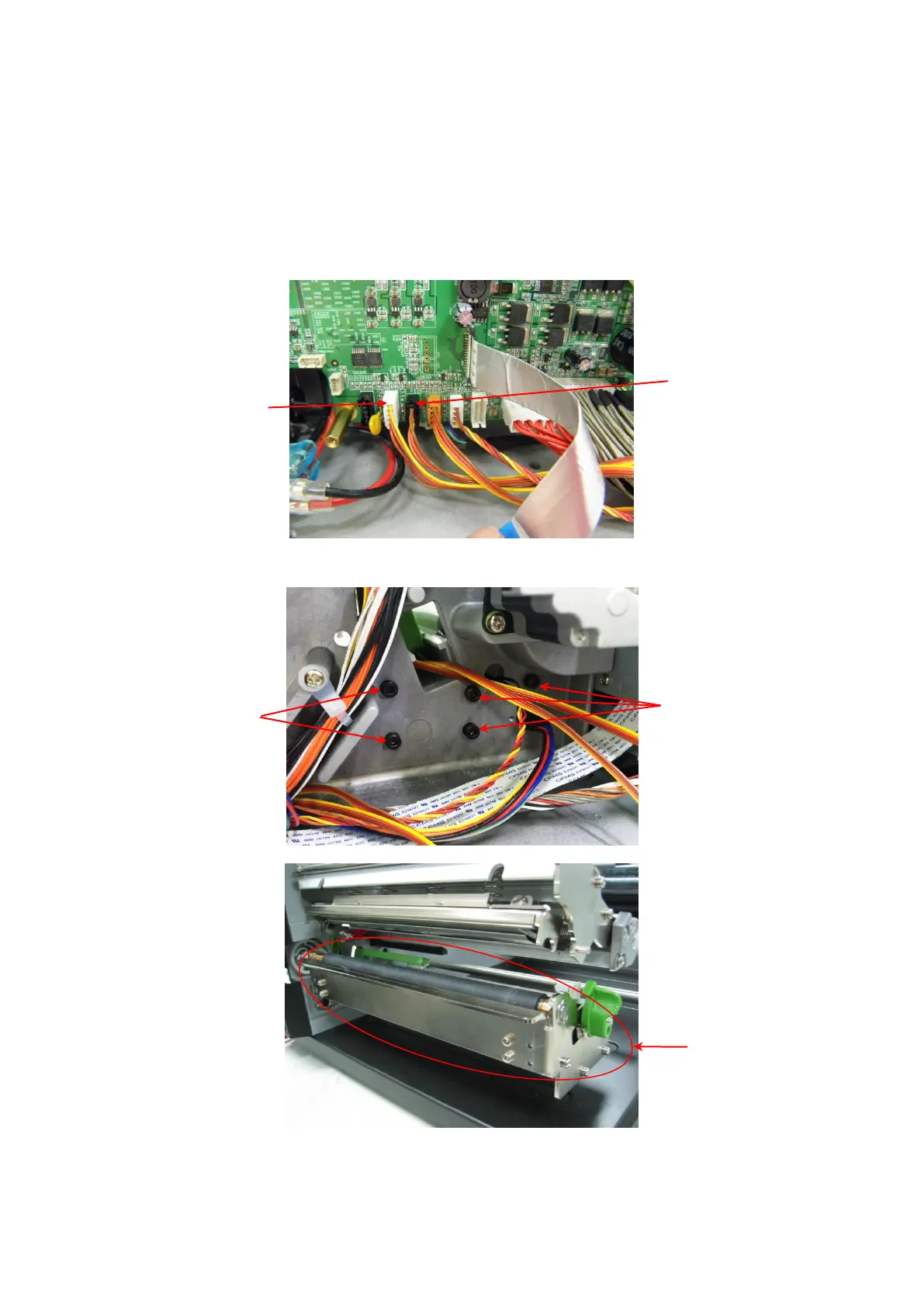
5. Remove 5 screws to take off the lower printhead mechanism.
6. Replace the sensor module.
7. Reassemble the parts in the reverse procedures.
Black-mark sensor
module connector
Gap sensor module
connector
Screws
Screws
Lower printhead
mechanism

Other manuals for TSC TTP-286MT Series

Questions and Answers:

Question and Answer IconNeed help?

Do you have a question about the TSC TTP-286MT Series and is the answer not in the manual?

TSC TTP-286MT Series Specifications

General IconGeneral
BrandTSC
ModelTTP-286MT Series
CategoryPrinter
LanguageEnglish

Related product manuals