EasyManua.ls Logo

TSI Instruments 5200 Series User Manual

TSI Instruments 5200 Series
51 pages
To Next Page IconTo Next Page
To Previous Page IconTo Previous Page
Page #30 background imageLoading...
Page #30 background image
22 Chapter 4
SBTxnnn.nn (Series 5300)
SBTxnn.nnn (Series 5200)
Backwards compatible with Series 4000
/
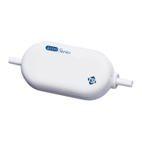
4100 flow meters.
Sets the begin-trigger level for starting the data acquisition.
SBT
Denotes set begin-trigger.
x
Denotes trigger source: F = flow (Std. L/min), P =
pressure (kPa), L = low pressure (cmH
2
O).

First sign denotes positive or negative slope. Second
sign denotes positive or negative trigger level.
+ = positive, - = negative.
nnn.nn
Set trigger level (“001.00” would denote 1.00 Std. L/min,
leading and trailing zeroes must be included). Negative
trigger levels can be set (“±001.00” would denote
-1.00 Std. L/min with positive slope).
The set trigger level stays in effect until cleared using the CBT
command. The trigger level is also cleared when the flow meter is
turned off or the DEFAULT command is initiated.
After the command is processed, an acknowledge sequence of “OK
<CR><LF> is sent. If the command generated an error, instead of
OK<CR><LF> being sent an error code of “ERRn<CR><LF> will
be sent. See Appendix A for a list of possible error codes.
Example 1) SBTF++002.00
Sets a begin-trigger level of 2.00 Std. L/min with positive slope.
Example 2) SBTP-+110.00
Sets a begin-trigger level of 110.0 kPa with negative slope.
Other manuals for TSI Instruments 5200 Series

Question and Answer IconNeed help?

Do you have a question about the TSI Instruments 5200 Series and is the answer not in the manual?

TSI Instruments 5200 Series Specifications

General IconGeneral
Measurement TypeAir Velocity, Air Temperature
Air Velocity Range0 to 30 m/s
AccuracyAir Velocity: ±3% of reading or ±0.015 m/s (±3 ft/min), whichever is greater; Air Temperature: ±0.5 °C (±1 °F)
Resolution0.1 °C for air temperature
Data LoggingYes
DisplayLCD with backlight

Summary

Chapter 1: Flow Meter Identification

Meter Front

Identifies components on the front view of the flow meter.

Meter Back

Identifies components on the back view of the flow meter.

Chapter 2: Connecting Computer to Flow Meter

Direct USB NDIS Interface

Details the process of connecting using a direct USB link with an NDIS driver.

RS232 Communication Utilizing a USB A to RS232 Adapter

Explains how to establish communication via RS232 using a USB to RS232 adapter.

Chapter 3: ASCII Protocol

Command Format

Defines the structure and case-sensitivity rules for ASCII serial interface commands.

Chapter 4: Command Set

Commands for Flow Rate, Temperature, Pressure, and Volume

Lists commands for retrieving flow, temperature, and pressure data.

Measurement Setup Commands

Details commands for configuring measurement triggers and sample rates.

Miscellaneous Commands

Covers commands for serial number, default settings, and aliases.

Display Commands

Explains commands used to control the LCD display update rate.

Chapter 5: Troubleshooting

Frequently Asked Questions

Technical Contacts

Related product manuals