DSO GAIN calibration:
Gain calibration is done to increase the measurement accuracy of the oscilloscope. To calibrate, first click
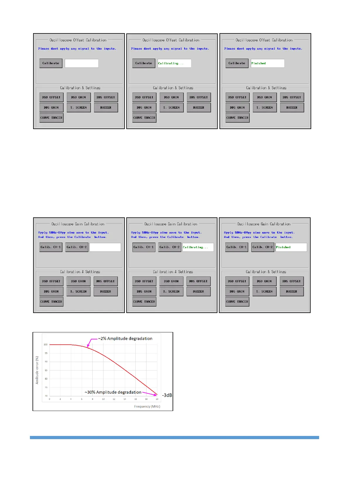
the “DSO GAIN” button. After the 50Hz-6Vpp sine reference signal is applied to the input in the submenu,
an information message indicating that the calibration process should be performed is displayed.
There are two buttons in the submenu. To calibrate Channel 1, apply the reference signal to the CH-1 input
and click the “Calib. CH-1” button. Then, the reference signal is applied to the CH-2 input and the
calibration process is completed by clicking the “Calib. CH-2” button.
Important note: As the frequency of the measured signal increases, the amplitude weakens. While
determining the bandwidth of the oscilloscopes, the
frequency value at which the measured signal
power is weakened by -3dB is taken as a basis.
Expressed in terms of voltage, this corresponds to
about 30% attenuation. A 20 MHz oscilloscope is
generally guaranteed to have less than 30%
attenuation at 20 MHz. To achieve voltage accuracy
better than 2% on the UCE-DSO4200C, the
frequency of the signal applied to the inputs must
be less than 7 MHz.