The calibration process consists of 10 steps. Click the “START” button to start.
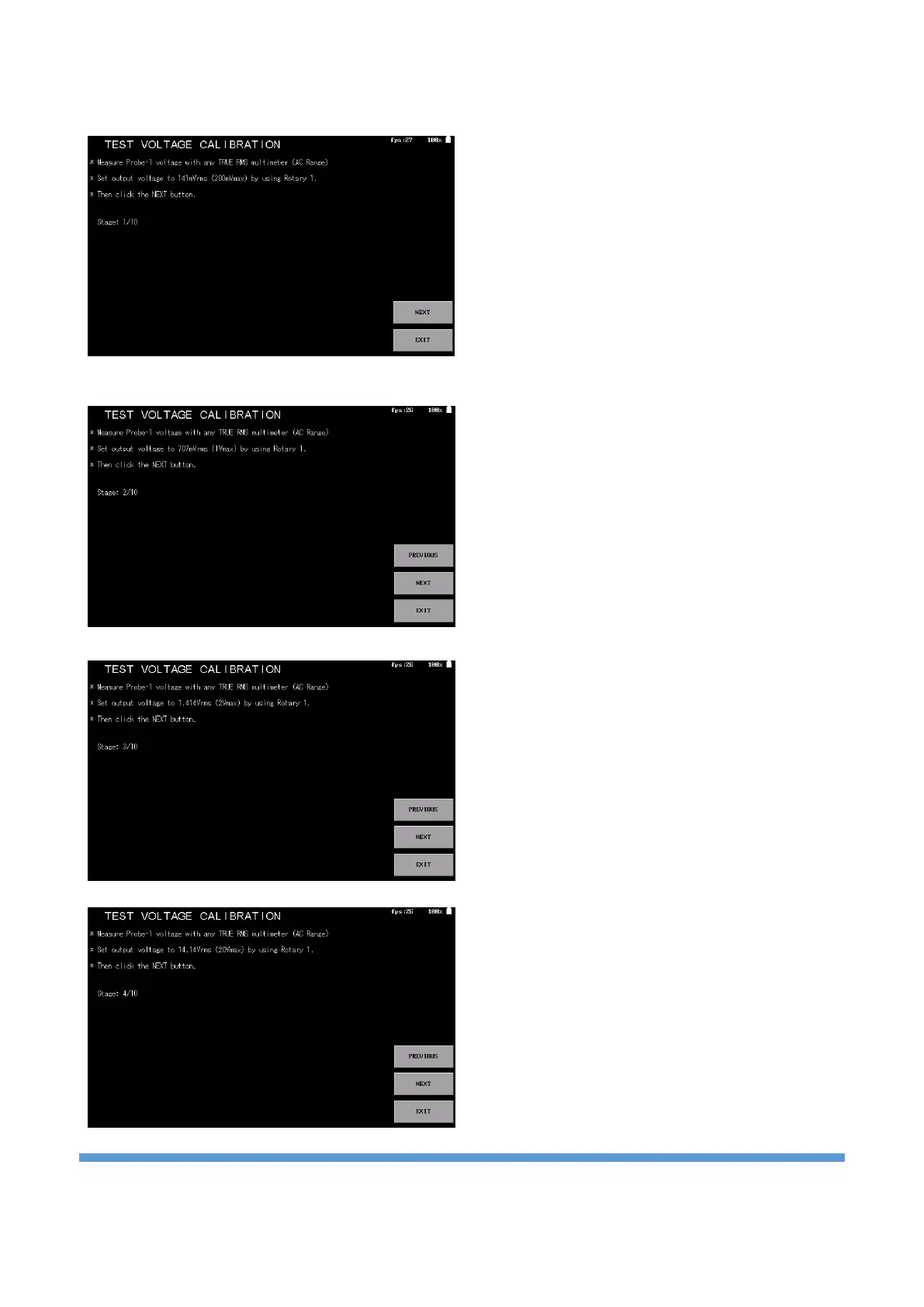
In the first stage, it is requested to measure the
Probe-1 input with a multimeter and set the output
voltage to 141mVrms. A multimeter with TRUE RMS
feature is connected to the Probe-1 and the
measurement is made in AC range. Rotate the
Rotary-1 (clockwise to increase, counterclockwise to
decrease) until the multimeter reads 141mVrms. If
the mouse is actively used, adjustment can also be
made by turning the scroll. After the adjustment is
made, the “NEXT” button is clicked to proceed to
the next step.
In the second stage, the output voltage is adjusted
as 707mVrms, similar to the previous one, and then
the “NEXT” button is clicked. If there is a need to
make corrections in the previous level, the
"PREVIOUS" button is clicked.
In the 3rd stage, the output voltage is adjusted to
1.41Vrms and then the “NEXT” button is clicked to
proceed to the next stage.
In the 4th stage, the output voltage is set to
14.14Vrms and then the “NEXT” button is clicked to
proceed to the next stage.