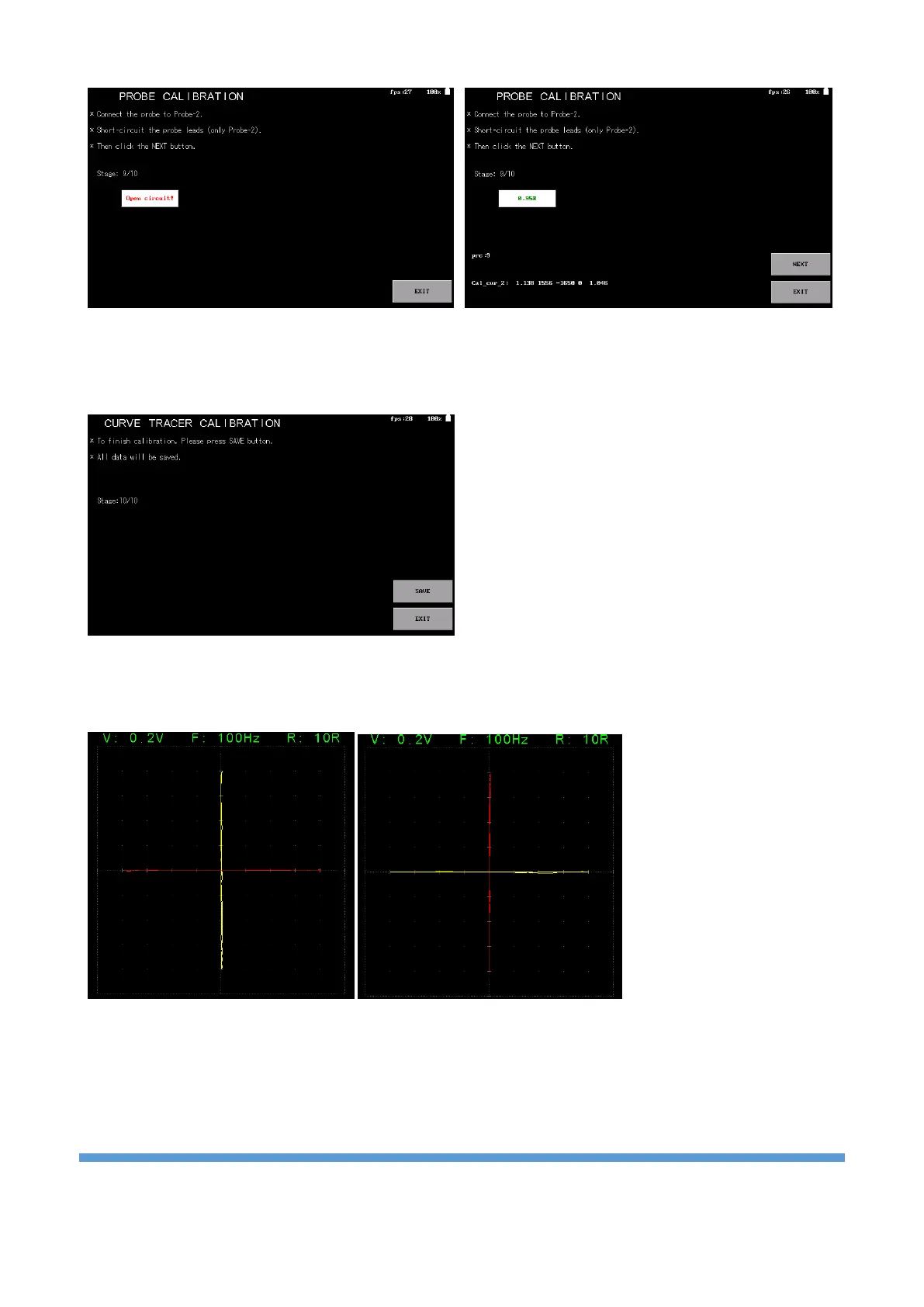
In the 9th step, probe calibration is performed. The probes of the device are connected to the probe-2
input and the terminals are short-circuited. When short-circuited, the impedance value is seen and the
“NEXT” button becomes active. Clicking the button will move to the next step.
In the 10th and last stage, the calibration data is
saved to the disk. By clicking the “SAVE” button, the
data is saved and the calibration is completed. Click
the “EXIT” button to exit the menu.
Whether the calibration is done correctly or not can be checked from the curve tracer menu. It is especially
recommended that the test be performed at the 10R range. Calibration is successful if Probe-1 and Probe-2
channels are open and short-circuit curves look like below.