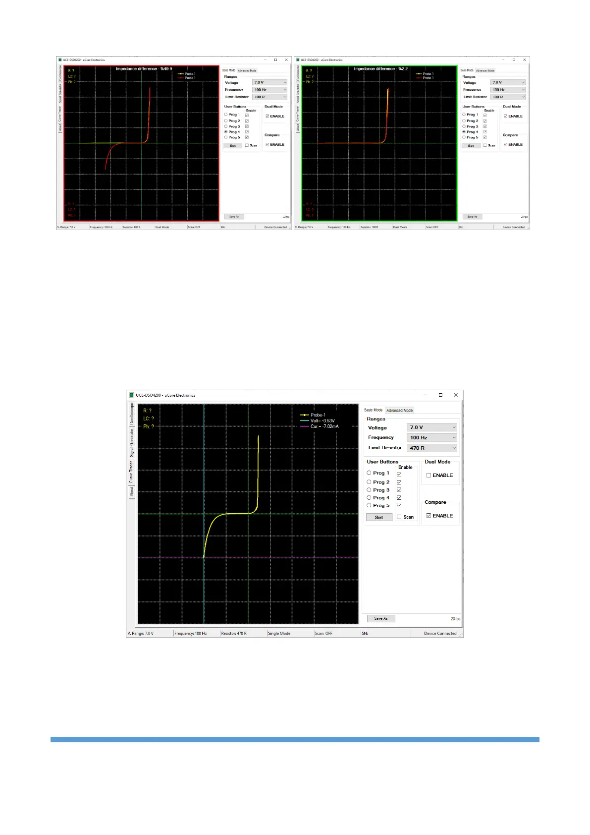
Figure 19. Two channel comparison in Dual Mode
When “Compare” is active, the comparison algorithm is also active. The impedance curve in both channels
is compared with the algorithm. As a result of the comparison, a percentage value called “Impedance
difference” is calculated. If this value exceeds the tolerance value (Figure 18) set in the “Advanced Mode”
tab, the comparison will fail and a red frame will appear around the graphics area. If the comparison is
successful, a green frame is formed (Figure 19).
If the “Audible warning” checkbox in the “Advanced Mode” tab is checked, it gives a different sound
warning in case of success and failure as a result of the comparison.
Figure 20. Analysis with Cursor
Cursor analysis becomes active when left-clicking anywhere on the graphics area. Two cursors appear on
the graph. The vertical one is for the voltage and the horizontal one is the current. The current and voltage
values at the intersection of the two cursors are seen in the upper right of the graph. With this feature,
precise measurements can be made on the impedance curve. Cursors and measurement values become
inactive when changing the test stage or right-clicking.