UT25CL User Manual
18
7.1 Track Energized and Deenergized Cables
7.1.1 Connect test leads to the transmitter
1. Connect the black and red test leads to the transmitter (No need to consider the polarity).
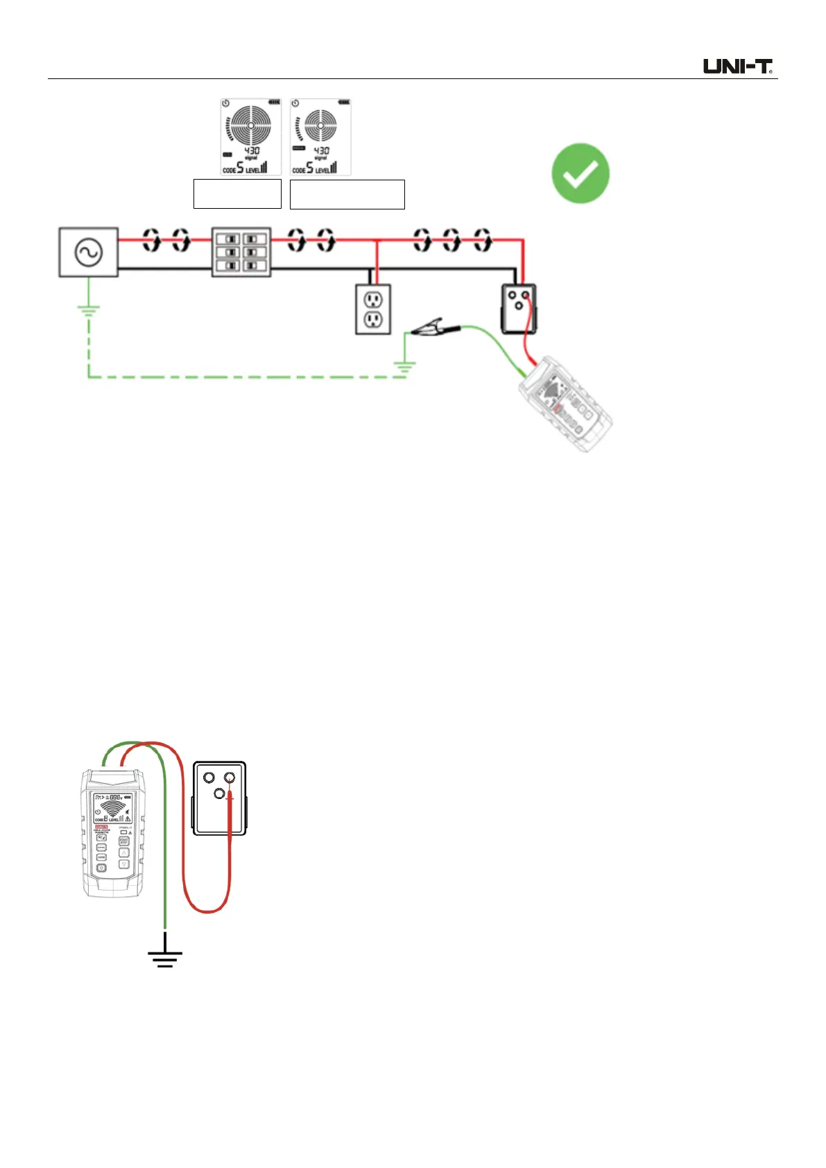
2. Connect the outlet convertor to the outlet, and connect the red test lead to the energized live wire
(at the load side of the system). Signal is generated only between the power supply and the load
side connected with the transmitter. As shown in Figure 7.1.1a.
Figure 7.1.1a Correct Connection of Independent Grounding
3. Connect the black test lead to the independent grounding (metal structure of building, metal water
pipe, or grounding wire of independent circuit)
 Loading...