UT25CL User Manual
33
9. External Voltage Measurement and ELV Function (UT25CL-T)
9.1 External Voltage Measurement
1. When the transmitter is in power-on state. Regardless of whether the transmitter transmits signal
or not (Some sources will be interfered when transmitting signal. If voltage source is sensitive
to the interference, please stop transmitting signal immediately).
2. Connect the red test cable with probe (or the red of polarized plug) to the terminal (V+ port) of
the transmitter.
3. Connect the black test cable with probe (or the black of polarized plug) to the terminal (COM
port) of the transmitter.
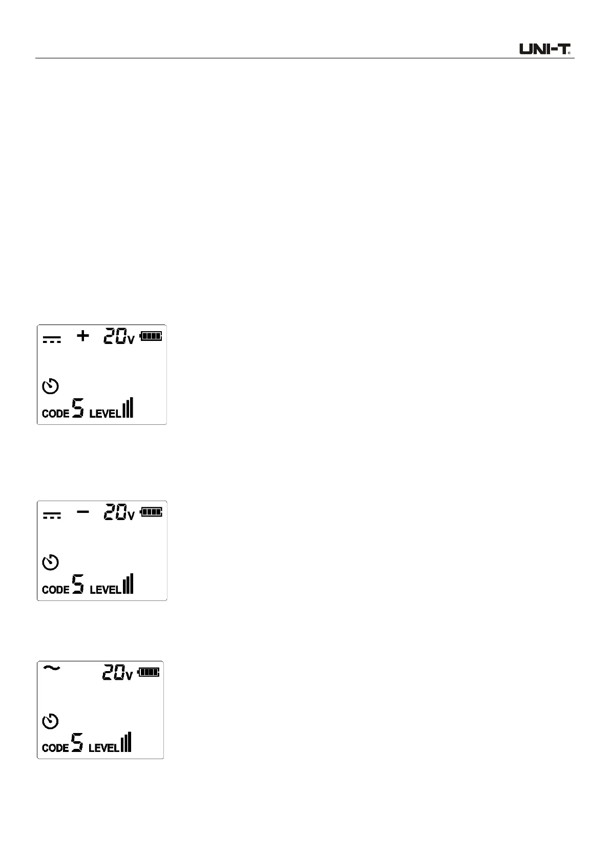
4. When the voltage is 8 V ~ 480 V DC/AC (50/60 Hz). If the measured voltage is DC voltage and
the positive pole is connected to V+ port, then the polarity of the port will be displayed (the
polarity of V+ port is “+”). As shown in Figure 9.1a.
Figure 9.1a DC voltage measurement
5. When the voltage is 8 V ~ 480 V DC/AC (50/60 Hz). If the measured voltage is DC voltage and
the positive pole is connected to COM port, then the polarity of the port will be displayed (the
polarity of V+ port is “-”). As shown in Figure 9.1b.
Figure 9.1b DC voltage measurement
6. When the voltage is 8 V ~ 480 V DC/AC (50/60 Hz). If the measured voltage is AC voltage, then
the display is as shown in Figure 9.1c.
Figure 9.1c AC voltage measurement