UT25CL User Manual
24
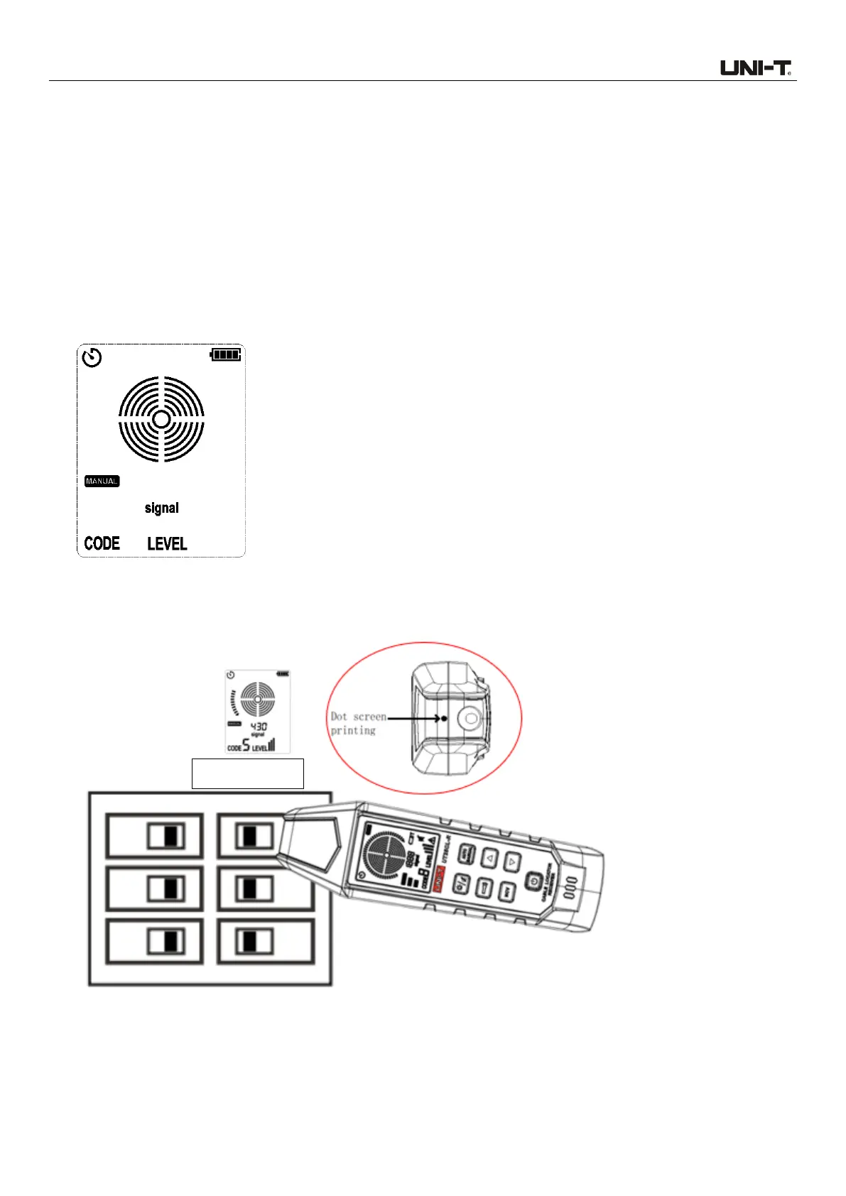
Figure 7.2.2a
Note: To locate the cable more accurately, please set the transmission strength to II, to limit
the level of the signal generated by the transmitter. Relatively-low signal level can reduce
coupling with adjacent cables and metal objects, which avoids incorrect reading caused by
ghost signal. Relatively-low signal level also helps to prevent the receiver from being
oversaturated due to large covering area of strong signal.
7.2.3 Use of UT25CL-R receiver
1. Power on the receiver and then short press the AUTO/MANUAL button to switch to manual mode,
as shown in Figure 7.2.3a.
Figure 7.2.3a No Signal Detected
2. Align the dot screen printing (on the top of the receiver) to the circuit breaker, as shown in Figure
7.2.3b.
Figure 7.2.3b Align the dot screen printing to the circuit breaker
3. Scan all circuit breakers in random sequence. Scan the circuit breakers multiple times to observe
the signal strength displayed on the LCD, until a circuit breaker panel with strongest signal is
identified. During scanning, the sensitivity needs to be adjusted repeatedly, to prevent the
 Loading...