UT25CL User Manual
23
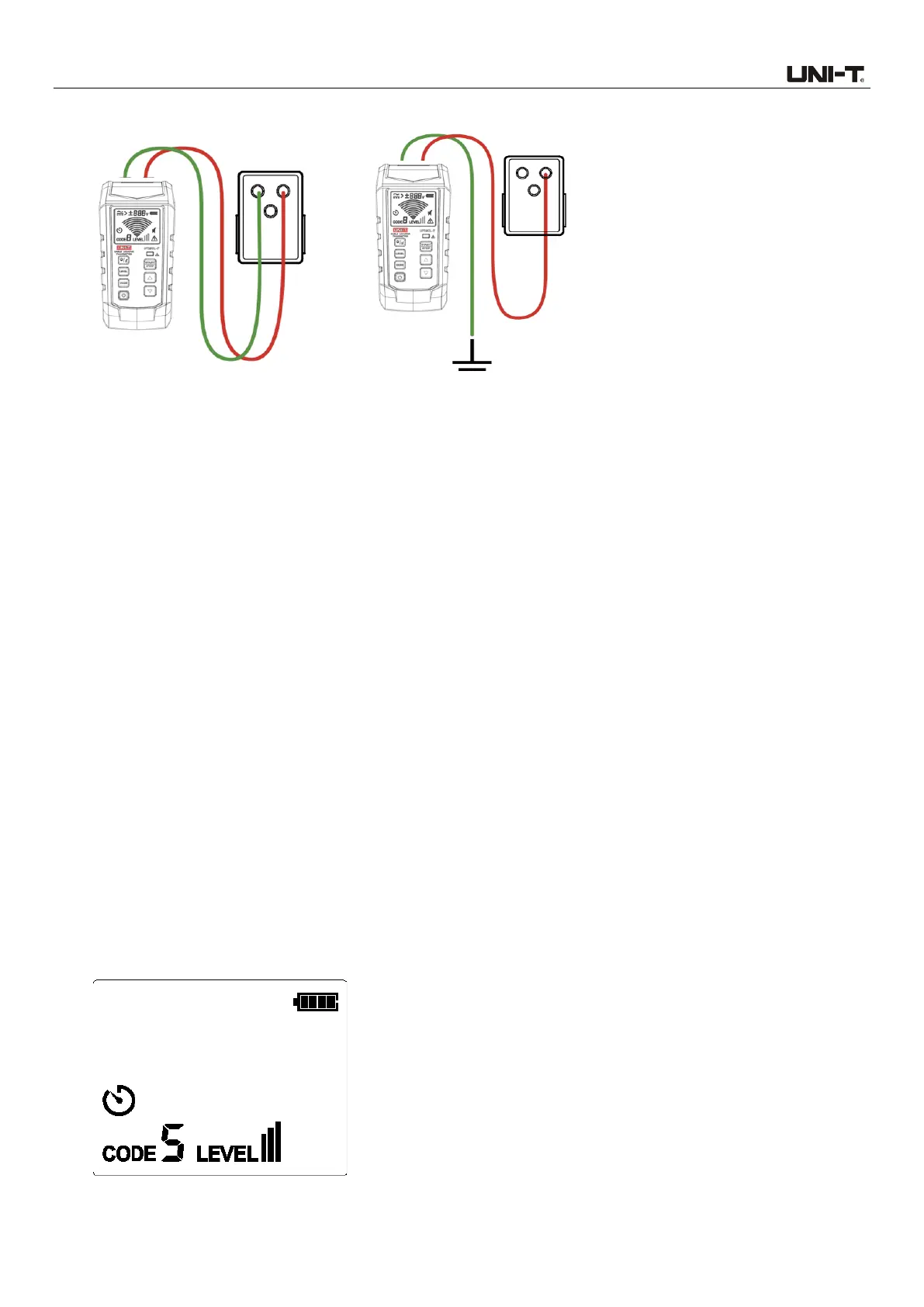
Figure 7.2a Simple Connection Figure 7.2b Independent Grounding (Preferred choice)
7.2.1 Connect test leads
1. Connect the transmitter through simple connection or independent grounding.
2. Through simple connection: Connect the test lead to live or neutral wire directly. Since signals
counteract mutually, cable cannot be tracked when locating circuit breaker.
3. Through independent grounding: Connect the red test lead to the energized live wire at the load
side of the system. Signal is generated only between the power supply and the outlet connected
with transmitter.
4. Connect the black test lead to independent grounding, i.e., metal structure of building, metal water
pipe, or grounding wire of independent circuit.
7.2.2 Use of UT25CL-T transmitter
1. Power on the transmitter.
2. Test and confirm if the connection of test leads is correct. For circuit with voltage over 30 V AC/DC,
the warning symbol will light up; for deenergized and energized circuit with voltage below 30V AC/DC,
the warning symbol will light off. Note: Please perform connection through the above-mentioned
independent grounding.
3. For most applications, the default transmission strength is III (default code: 5). As shown in Figure
7.2.2a, the level shown on the LCD is III.
 Loading...