UT25CL User Manual
19
Note: If applied to GFCI-protected circuit, this method will trigger GFCI. Please see “Special
Applications”. For the tracking method, please see the Section 8.1 “Track the Cable of GFCI-
Protected Circuit”
7.1.2 Setting of UT25CL-T transmitter
1. Power on the transmitter.
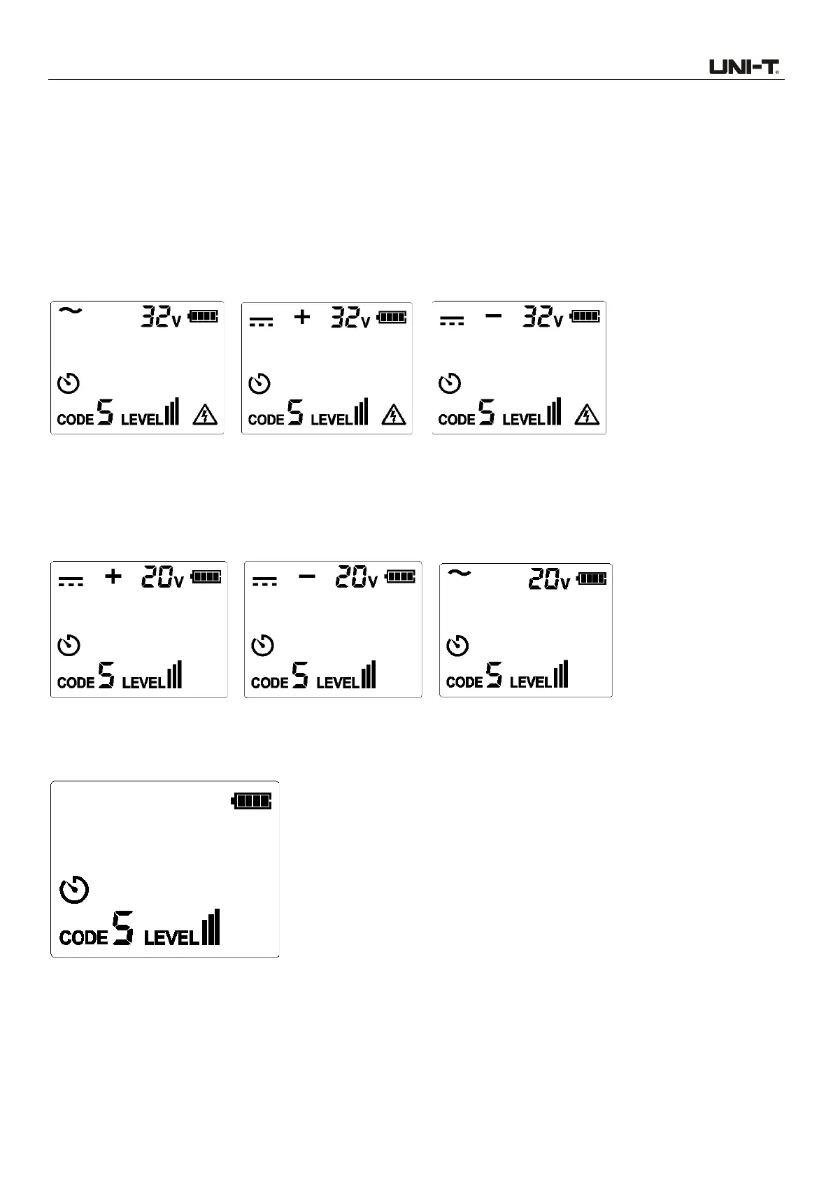
2. Test and confirm if the connection of test leads is correct. For circuit with voltage over 30 V AC/DC,
the warning symbol will light up. As shown in Figure 7.1.2a.
Figure 7.1.2a Voltage over 30V
For deenergized and energized circuit with voltage below 30V AC/DC, the warning symbol will light
off.
Note: Please perform connection through the above-mentioned independent grounding.
Figure 7.1.2b Voltage below 30V
3. For most applications, the default transmission strength is III (default code: 5). As shown in Figure
7.1.2c, the level shown on the LCD is III.
Figure 7.1.2c
Note: To locate the cable more accurately, please set the transmission strength to II or I (As
shown in Figures 7.1.2d and 7.1.2e. For specific operating method, please see “6.1.2 LEVEL
Setting”), to limit the level of the signal generated by the transmitter. Relatively-low signal
level can reduce coupling with adjacent cables and metal objects, which avoids incorrect
 Loading...