UT25CL User Manual
9
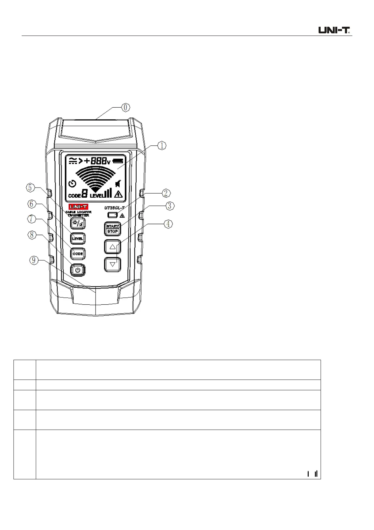
4. Transmitter Components
4.1 Transmitter Appearance
4.2 Descriptions of Components
Input/output terminal: Used to connect with multiple accessories (i.e., AC polarized plug) for
signal measurement/output.
LCD screen with backlight.
ELV indicator light: If the voltage of the input port exceeds the specified voltage when the
transmitter is powered off, the LED lights up red and its brightness increases as the voltage rises.
Button for starting/stopping signal transmission: When there is no signal emitt
ed, short
press this button to start signal transmission, short press again to stop signal transmission.
Up/Down button (Enabled when transmission is stopped and the CODE and LEVEL are
set):
When the CODE symbol flashes, short press the Up/Down button to set the CODE to 0, 1,
2, 3, 4, 5, 6 or 7. The default code is 5.
When the LEVEL symbol flashes, short press the Up/Down button to set the LEVEL to ,