UT25CL User Manual
32
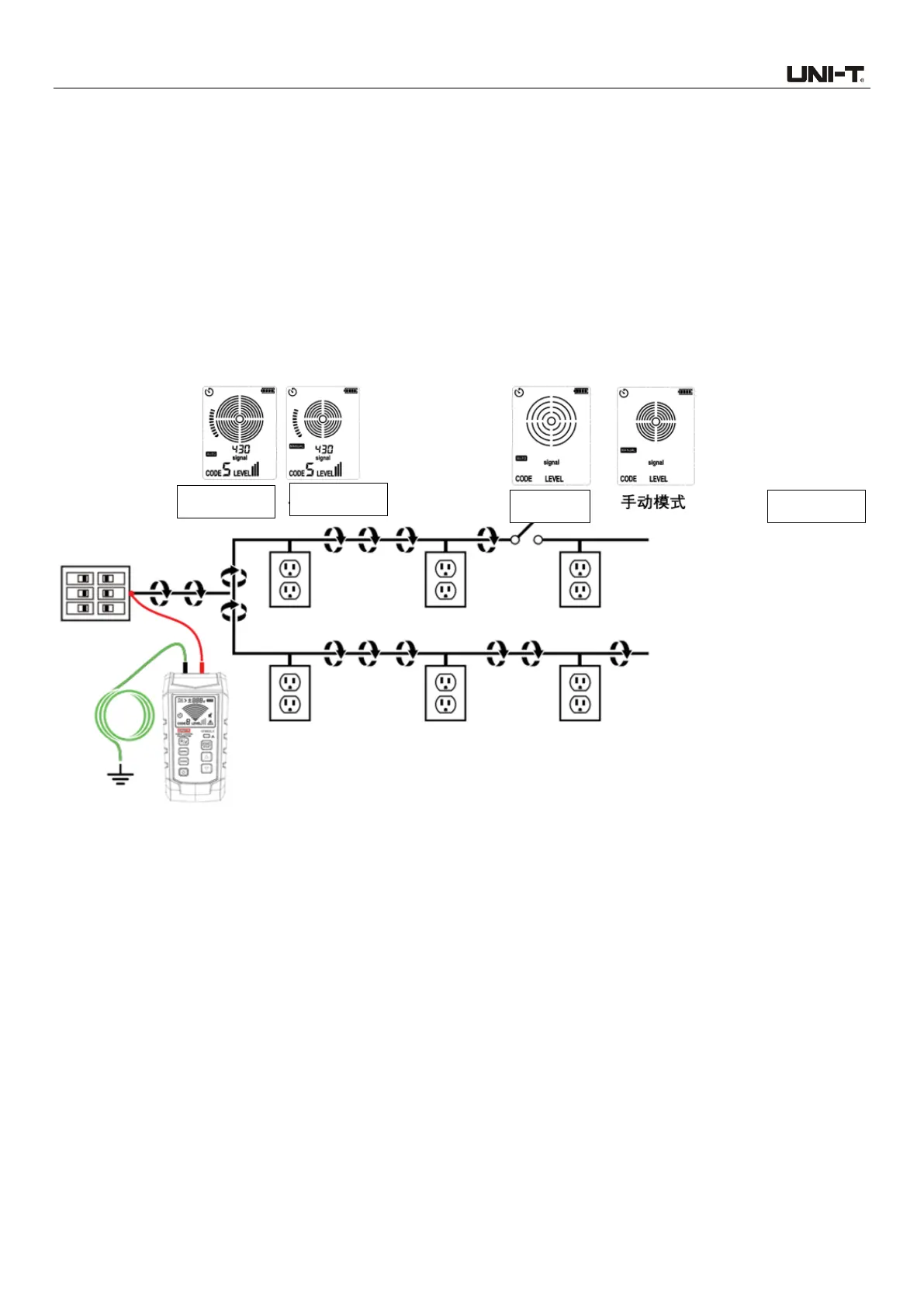
8.9 Draw a Circuit Diagram Using the Connection of Test Leads
For use of the connection of test leads, drawing a circuit diagram is applicable to deenergized
circuits only.
1. Set the circuit breaker to OFF (switch off) position.
2. Set the transmitter and the receiver according to the instructions of automatic or manual scanning
mode in Section 6.
3. Scan the outlet panel and the cable connected with load through the sensor of the receiver.
4. According to the indication of the receiver, all cables, outlets and loads with relatively strong
signals are connected to the circuit breaker.
5. See 8.9.1a for specific application.
Figure 8.9.1a Draw a circuit diagram using the connection of test leads
8.10 Track the Circuit Breaker in the System with Illumination Dimmer
Dimmer will make a large amount of electrical “noises”, including signals with multiple frequencies.
In a few cases, such noises (typically called “ghost” signal) are misread by the receiver as the signal
generated by the transmitter. Thus, the receiver may provide an incorrect reading. When locating
the circuit breaker or fuse in the system with dimmer, please turn off the dimmer (disconnect the
light switch), so as to effectively prevent the receiver from indicating a wrong circuit breaker or fuse.
 Loading...