UNIPOWER
UP-2210R/P Hardware installation and configuration manual
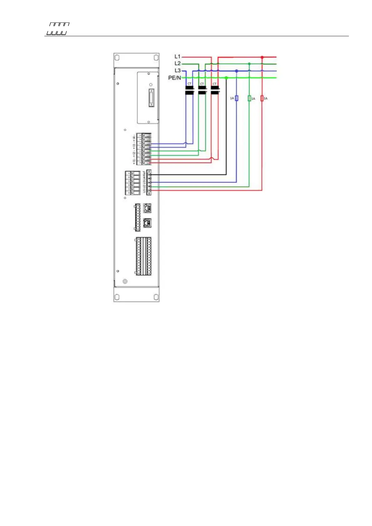
4.4.1 3 phase with 4 wire measurement with direct voltage and 3 CT’s
Figure 10
The above wiring diagram is used for 3-phase measurement in low voltage networks. The voltage
channel of the unit is connected directly to the electricity network for measuring line-to-neutral
voltage (230 V) and therefore do not require an instrument transformer (PT). The current channels
are connected to existing instrument transformers, allowing the measurement of high currents, e.g.
directly from the secondary side of a power transformer. Always protect the voltage inputs with a
suitable fuse in each conductor. The connection for this type of measurement is as follows:
Channel: Measured object: Channel: Measured object:
U1 = L1 I1+ = L1 CT+
U2 = L2 I1- = L1 CT-
U3 = L3 I2+ = L2 CT+
Ref = N (Neutral) I2- = L2 CT-
I3+ = L3 CT+
I3- = L3 CT-
 Loading...