UNIPOWER
UP-2210R/P Hardware installation and configuration manual
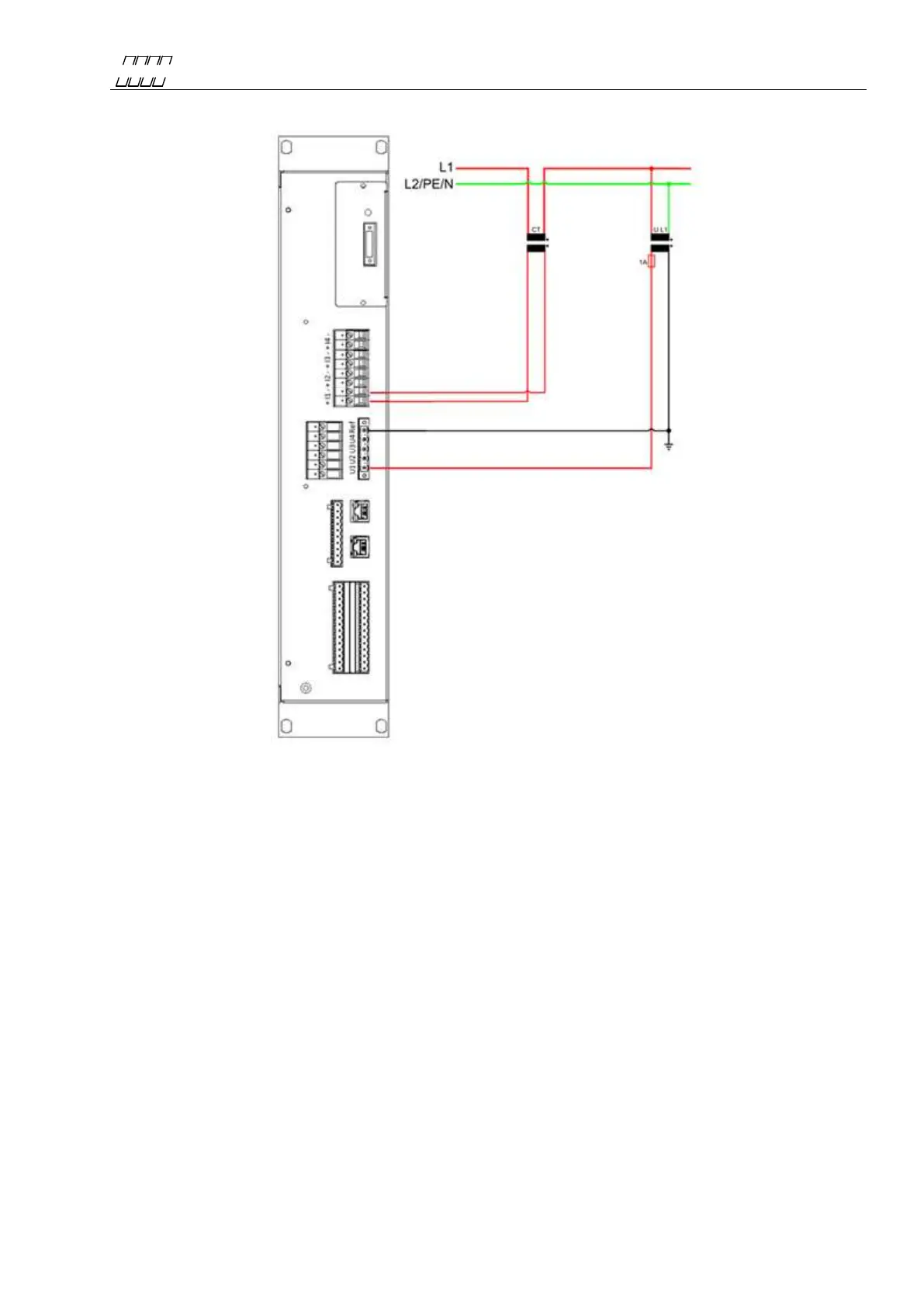
4.4.8 1-phase measurement with one PT and one CT
Figure 17
The above wiring diagram is used for single-phase measurement in public distribution networks with
one CT and one PT. The voltage channel of the unit is connected to PT for measuring line-to-neutral
voltage. The current channel is connected to existing instrument transformer, allowing the
measurement of high currents, e.g. directly from the secondary side of a power transformer. Always
protect the voltage inputs with a suitable fuse in each conductor. The connection for this type of
measurement is as follows:
Channel: Measured object: Channel: Measured object:
U1 = L1 PT+ I1+ = L1 CT+
Ref = L1 PT-(Grounded) I1- = L1 CT-
 Loading...