UNIPOWER
UP-2210R/P Hardware installation and configuration manual
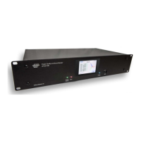
J. Power/status LED. Green indicates power on and all ok. Red indicates failing UST (Unit Self
Test). Contact your Unipower representative if you see red colour.
K. Sync LED. When blinking it indicates that time/clock is synchronised with GPS.
L. Colour touch screen.
M. Energy LED. Blinks corresponding to measured, consumed energy. Depending on meter
constant.
N. USB interface. Used for local connection to laptop/computer for configuration, data
download, service or real-time values.
Note: When connecting to CT or PT existing ones are preferably used. For new installations
we recommend same type/class as being used in metering circuits.
4.4 Connection alternatives
In the electric grid there are multiple configurations of instrument transformers (PT= Potential
Transformer, CT= Current Transformer). The UP-2210 meters support all standard 1-phase and 3-
phase connections. The meter is configured using PQ Online, where all the common connections
methods with their respective wiring diagrams available and a graphical explanation. Here it is also
possible to set the transformer ratios as constants.
 Loading...