UNIPOWER
UP-2210R/P Hardware installation and configuration manual
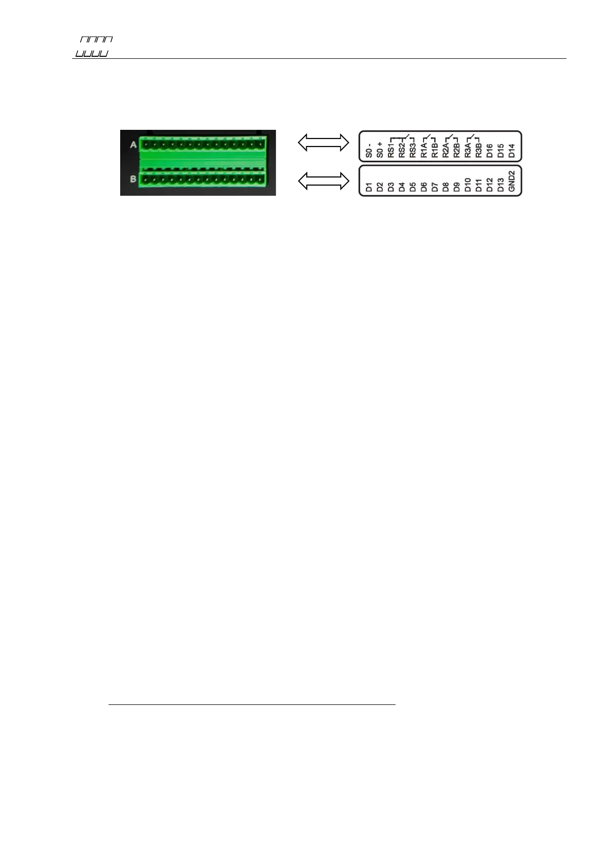
events, for example when the door of a particular station is opened or closed, the temperature,
status, etc. The digital inputs are easily configured using the PQ Online program.
S0 interface. 1 opto isolated S0 output for energy pulses.
B. Time/TTL IRIG-B interface. Optional.
Temperature inputs. 2 Pt-100 sensor inputs. Optional.
RS-485 interface. Optional.
C. RJ-45 connection for 10/100-BaseT Ethernet communication, which is available as an
option.
D. RJ-45 connection for secondary, independent 10/100-BaseT Ethernet communication, which
is available as an option.
E. Optional extra analogue inputs.
F. 4 isolated voltage inputs + reference (the range is stated on the label). The voltage inputs are
designed for the direct measurement of line-to-neutral voltages in low voltage networks as
well as for connection to potential transformers (PT) secondary circuit in high voltage
networks. Remember to connect the polarities correctly, because incorrect polarity will shift
the voltage signal 180°, affecting power calculations, unbalance and other parameters.
Connect the voltage channels in accordance with the wiring diagrams later in this manual.
Local installation regulation must always be considered. For stranded cables we recommend
fitting with an adapter.
G. 4 isolated current channels (the range is stated on the label). The current channels are
designed for direct connection to the existing current transformer (CT) secondary side. It is
important to connect the current channels with the correct polarity; otherwise power,
unbalance and other parameters will be incorrect. Connect the current channels in accordance
with the wiring diagrams shown later in this manual. Local installation regulation must
always be considered. For stranded cables we recommend fitting with an adapter.
H. Connection for Power Supply. Power supply is user replaceable on site. If a suitable DC
voltage source is available this is a preferred choice. If there is no station/internal battery
backup, Unipower recommends that you connect the instrument to an external UPS type
battery source in order to prevent power failure disturbances. Protect the feeding cable with a
2A fuse. Local installation regulation must always be considered. For stranded cables we
recommend fitting with an adapter. If an AC supply is used, the phase is connected to L input
and the neutral conductor is connected to the negative input, N on the UP-2210 meter.
Always ensure that the UP-2210 unit is grounded (earthed), using the input marked with the
ground symbol.
I. Ground terminal. Always connect this point to protective earth.
Figure 9
 Loading...