UNIPOWER
UP-2210R/P Hardware installation and configuration manual
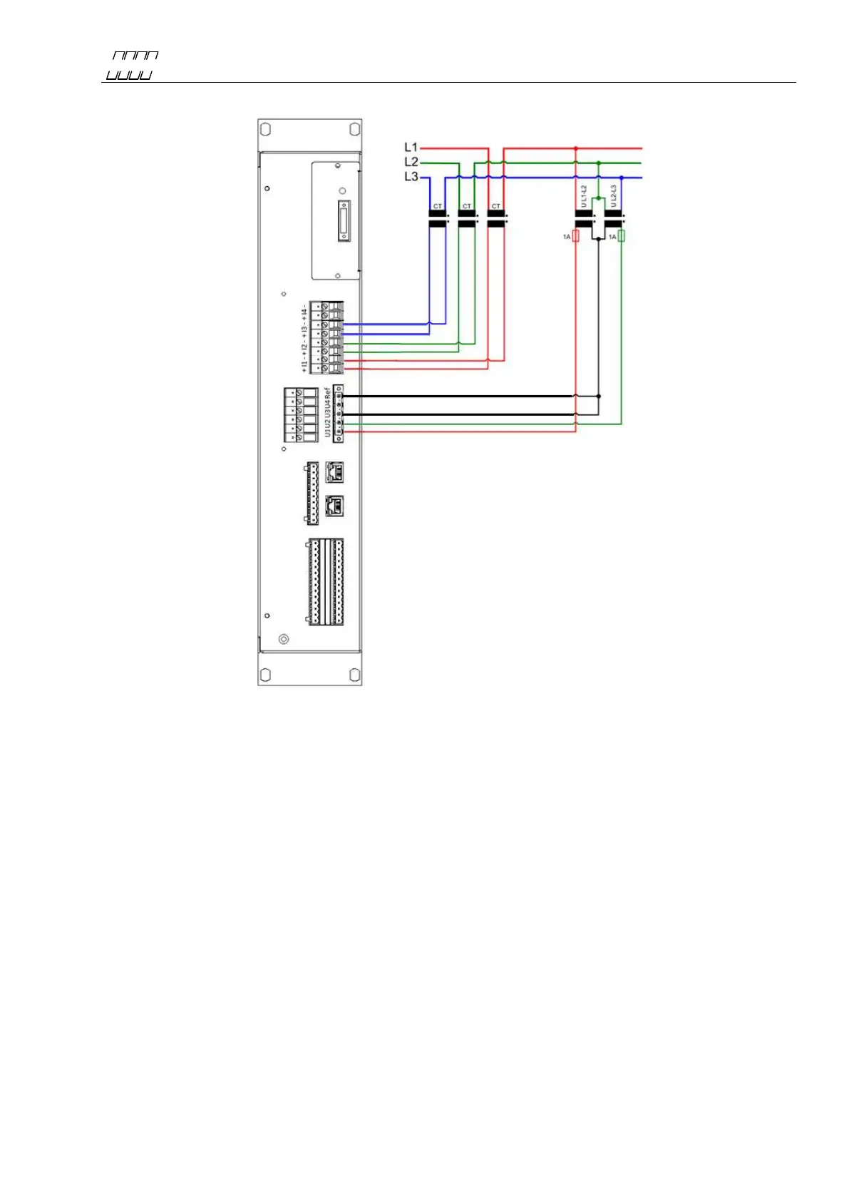
4.4.10 HV 3-phase measurement with 3 CT’s and 2 PT’s (Line-to-line voltages)
Figure 19
The above wiring diagram is used for three-phase measurement in public distribution networks with
3 CT´s and 2 PT’s. The voltage channels of the unit are connected to PT’s (normally 110 V AC
secondary), for supplying line-to-line voltages, and current channels are connected to CT’s (normally
1 - 5 A AC secondary). Two voltage channels are measured and the third is calculated in the
measuring device. Always protect the voltage inputs with a suitable fuse in each conductor on the
secondary side of the PT. The connection for this type of measurement is as follows:
Channel: Measured object: Channel: Measured object:
U1 = L1-L2 PT+ I1+ = L1 CT+
U2 = L2-L3 PT- I1- = L1 CT-
Ref = L1-L2 PT-, L2-L3 PT+ I2+ = L2 CT+
I2- = L2 CT-
I3+ = L3 CT+
I3- = L3 CT-
Note: If this method is used, the meter will automatically calculate the third line-to-line
voltage (U
L3 - L1
). This configuration is normally used in medium voltage networks.
 Loading...