2.3. The Safety Interface
The Simplest Emergency Stop Configuration
24V 24V GND GND
E01 E02 E03 E04
SA SB A R
TA TB A R
GND GND GND GND
24V 24V DO0 DO1
GND GND GND GND
DO2 DO3 DO4 DO5
GND GND DI0 DI1
DO6 DO7 24V 24V
DI2 DI3 DI4 DI5
24V 24V 24V 24V
DI6 DI7 A0- AO+
24V 24V A1- A1 +
EA EB EEA EEB
TA TB TA TB
AG AO0
AG AO1
E01 E02 E03 E04
EA EB EEA EEB
TA TB TA TB
GND GND
DO7 24V
GND
GND
DI0 DI1 DI2
24V 24V 24V
Button
LO AD
LO AD
GND GND
DO0 DO1
GND GND GND GND
DO2 DO3 DO4 DO5
GND GND
DO6 DO7
GND GND
24V 24V DO0
LO AD
GND GND
DO0 DO1
GND GND GND GND
DO2 DO3 DO4 DO5
GND GND
DO6 DO7
GND GND
24V 24V DO0
24V
Emergency
Stop
E01 E02 E03 E04
EA EB EEA EEB
TA TB TA TB E01 E02 E03 E04
EA EB EEA EEB
TA TB TA TB
A B
24V 24V GND GND SA SB A R
TA TB A R
24V 24V GND GND SA SB A R
TA TB A R
24V 24V GND GND SA SB A R
TA TB A R
24V 24V
24V GND
GND GND SA SB A R
TA TB A R
GND GND
DO0 DO1
GND GND GND GND
DO2 DO3 DO4 DO5
GND GND
DO6 DO7
24V
E01 E02 E03 E04
EA EB EEA EEB
TA TB TA TB
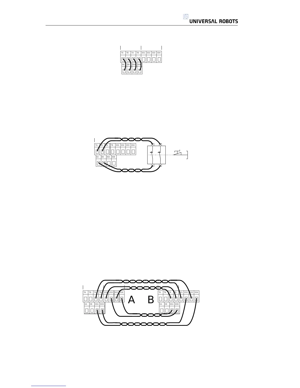
The simplest configuration is to use the internal emergency stop button as
the only component to generate an emergency stop. This is done with the
configuration shown above. This configuration is the default when the robot
leaves the factory, and thereby the robot is ready to operate. However, the
emergency configuration should be changed if required by the risk assessment.
Connecting an External Emergency Stop Button
E01 E02 E03 E04
EA EB EEA EEB
TA TB TA TB
In almost every robot application it is required to connect one or more exter-
nal emergency stop buttons. Doing so is simple and easy. An example of how
to connect one extra button is shown above.
Connecting Emergency Stop to Other Machinery
When the robot is used together with other electro-mechanical machinery, it is
often required to set up a common emergency stop circuit. This ensures that if
a dangerous situation arises, the operator does not need to think about which
buttons to use. It is also often preferable for every part of a sub-function in a
product line to be synchronized, since a stop in only one part of the product
line can lead to a dangerous situation.
An example with two UR robots emergency stopping each other is shown
below.
E01 E02 E03 E04
EA EB EEA EEB
TA TB TA TB E01 E02 E03 E04
EA EB EEA EEB
TA TB TA TB
A B
An example where multiple UR robots share their emergency stop function is
shown below. Connect more robots as robot number 2 is connected.
This example uses 24V which works with many other machines. Make sure to
comply with all electrical specifications when UR robots share emergency stop
with other machinery.
All Rights Reserved
17 UR10

 Loading...


