Electric Specifications
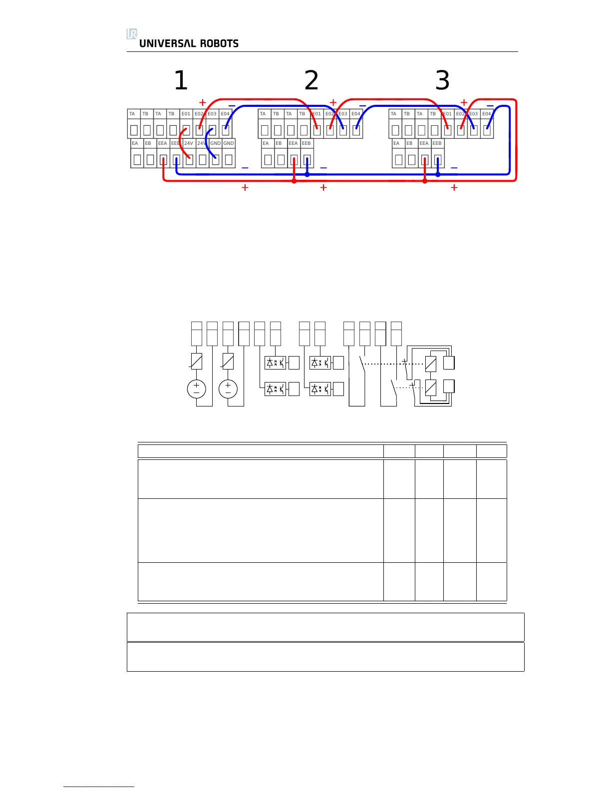
A simplified internal schematic of circuitry is shown below. It is important to no-
tice that any short circuit or lost connection will lead to a safe stop, as long
as only one error appears at a time. Failure and abnormal behavior of relays
and power supplies results in an error message in the robot log and prevents the
robot from powering up.
Below: Specifications of the Emergency Stop Interface.
Parameter Min Typ Max Unit
[TA-TB] Voltage 10.5 12 12.5 V
[TA-TB] Current (Each output) - - 120 mA
[TA-TB] Current protection - 400 - mA
[EA-EB][EEA-EEB] Input voltage -30 - 30 V
[EA-EB][EEA-EEB] Guaranteed OFF if -30 - 7 V
[EA-EB][EEA-EEB] Guaranteed ON if 10 - 30 V
[EA-EB][EEA-EEB] Guaranteed OFF if 0 - 3 mA
[EA-EB][EEA-EEB] ON Current (10-30V) 7 - 14 mA
[EO1-EO2][EO3-EO4] Contact Current AC/DC 0.01 - 6 A
[EO1-EO2][EO3-EO4] Contact Voltage DC 5 - 50 V
[EO1-EO2][EO3-EO4] Contact Voltage AC 5 - 250 V
Note the number of safety components that should be used and how they must
work depend on the risk assessment, which is explained in section 3.1.
Note that it is important to make regular checks of the safety stop functionality
to ensure that all safety stop devices are functioning correctly.
The two emergency stop inputs EA-EB and EEA-EEB are potential free inputs
conforming to IEC 60664-1 and EN 60664-1, pollution degree 2, overvoltage cat-
egory II.
The emergency stop outputs EO1-EO2-EO3-EO4 are relay contacts conform-
ing to IEC 60664-1 and EN 60664-1, pollution degree 2, over-voltage category
III.
All Rights Reserved
18 UR10