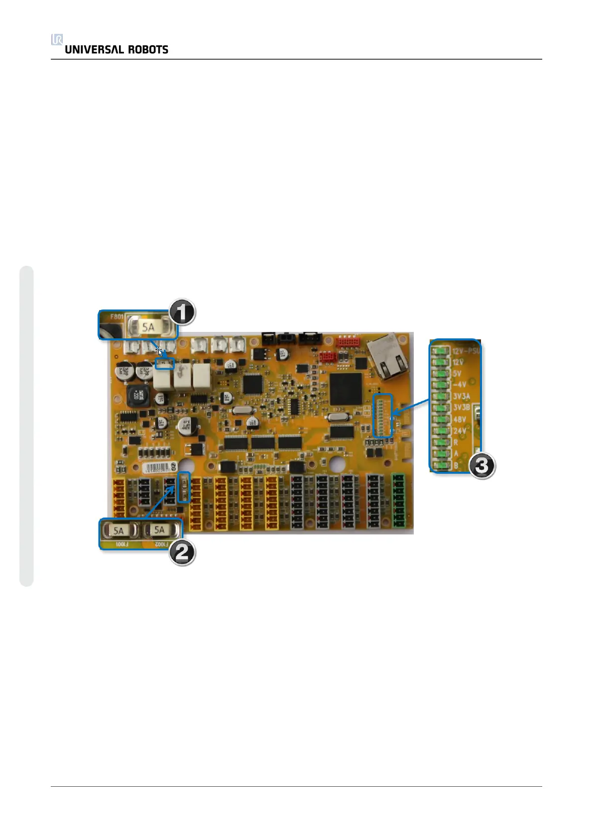
• 12V-PSUOn when the power plug is connected.
• 12VSystem: On when the main controller power has been activated.
• 5VOn when “12V System” is on and indicates that 5V is present.
• -4VOn when “12V System” is on and indicates that – 4V to analog I/O is present.
• 3V3A On when 5V is on and indicates 3.3V for logic Safety circuit A is present.
• 3V3BOn when 5V is on and indicates 3.3V for logic Safety circuit B is present.
• 48V Indicates 48 V is present on the Safety Control Board
• 24V 48V is detected and ok, indicates that internal 24 V is present for I/Os
• R 48 V present on robot arm
• A Indicates Status for Logic A: a blink sequence
• BIndicates status for Logic B: a blink sequence
7.2.1. Normal Startup Sequence for a CB3.x UR5
1. The 12V-Power supply LED is on when the power plug is connected to a working power
supply.
2. When the power button on the teach pendant is pressed, all LED indicators are turned on
except for the 48V, 24V and R LEDs. The A and B LEDs also exhibit a special behavior by
intermittently turning off and on ("blinking") once triggered.
3. The final phase of the startup sequence occurs (immediately) after the Polyscope software
is done loading. At this stage, the 48V and 24V LED indicators become active (are switched
on).
UR5 200 Service Manual
7.Troubleshooting
Copyright © 2009–2021 by UniversalRobotsA/S. All rights reserved.