8. Carefully attach the aluminum cover, making sure to mount it correct and fix it with the 5
screws.
If unsure of the correct positions consult Electrical Drawing
5.3.5. Replacement of Teach Pendant
Original Control Box
WARNING
Before replacing ANY components inside the control box, it is IMPORTANT to do
a complete shutdown.
Follow the first 3 steps in section Complete rebooting sequence.
When completing the following replacement, please follow the guidelines laid out in section
Handling ESD-sensitive parts.
NOTE
Use the same procedure for power down and removing the aluminum cover plates
as in chapter, Replacement of Motherboard 3.0, Replacement of Motherboard 3.1
or Replacement of Safety Control Board
1. Disconnect 4 cables:
1. Red plug with black cable 12 V Power
2. Black DVI cable for the TP screen
3. Black USB cable For the TP USB connector
4. Black cable for RS232-connection for the TP touchscreen
See diagram: Schematic overview.
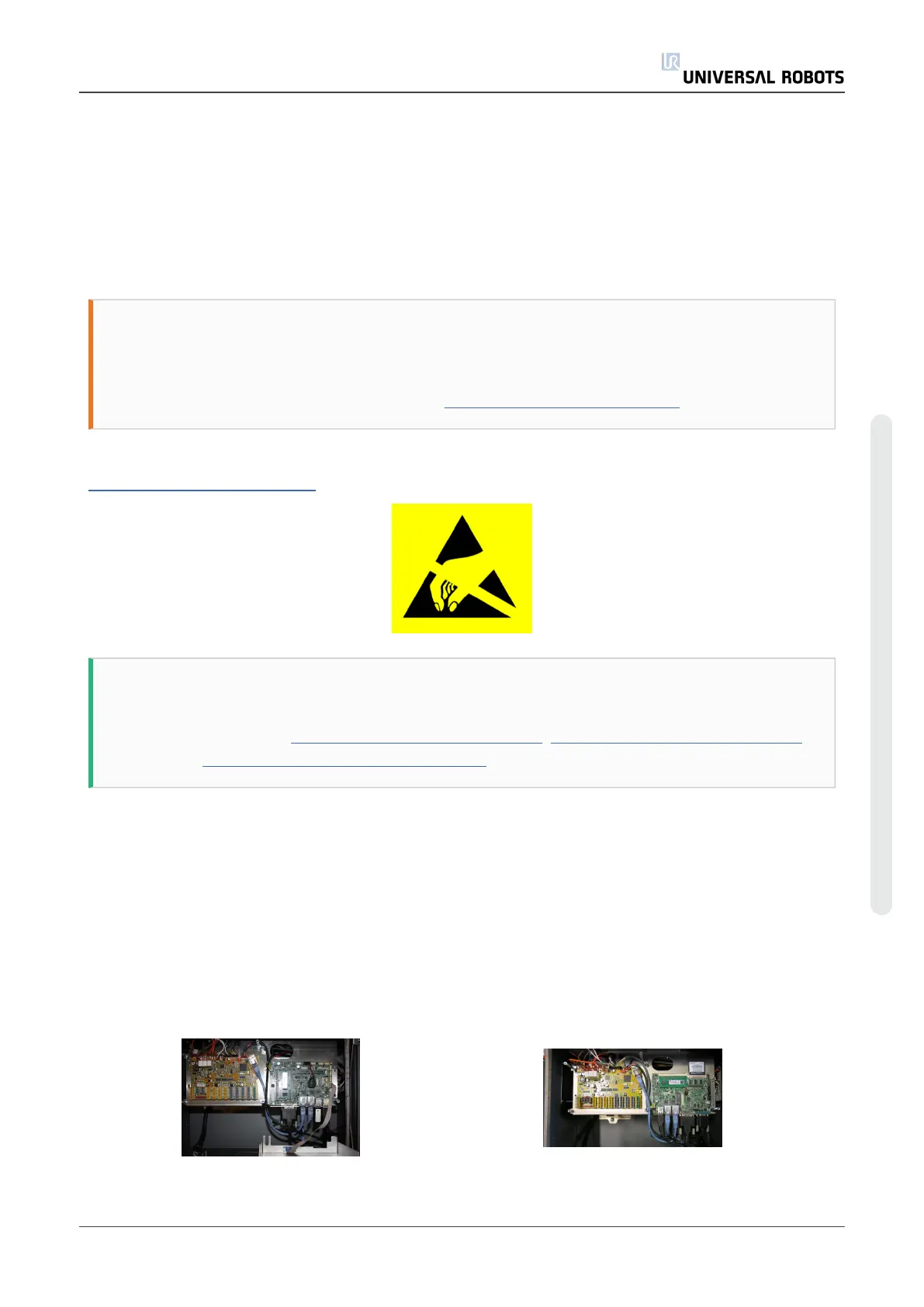
Motherboard 3.1 Motherboard 3.0
Service Manual 67 UR5
5.Service and Replacement of parts
Copyright © 2009–2021 by UniversalRobotsA/S. All rights reserved.