5. DVI-cable for Teach Pendant screen
6. Black cable for RS232-connection for Teach Pendant touch
4. Remove the 4 screws from the 2 holding brackets.
5. If controller is equipped with long-hole brackets, make sure to replace them with circular-
hole brackets
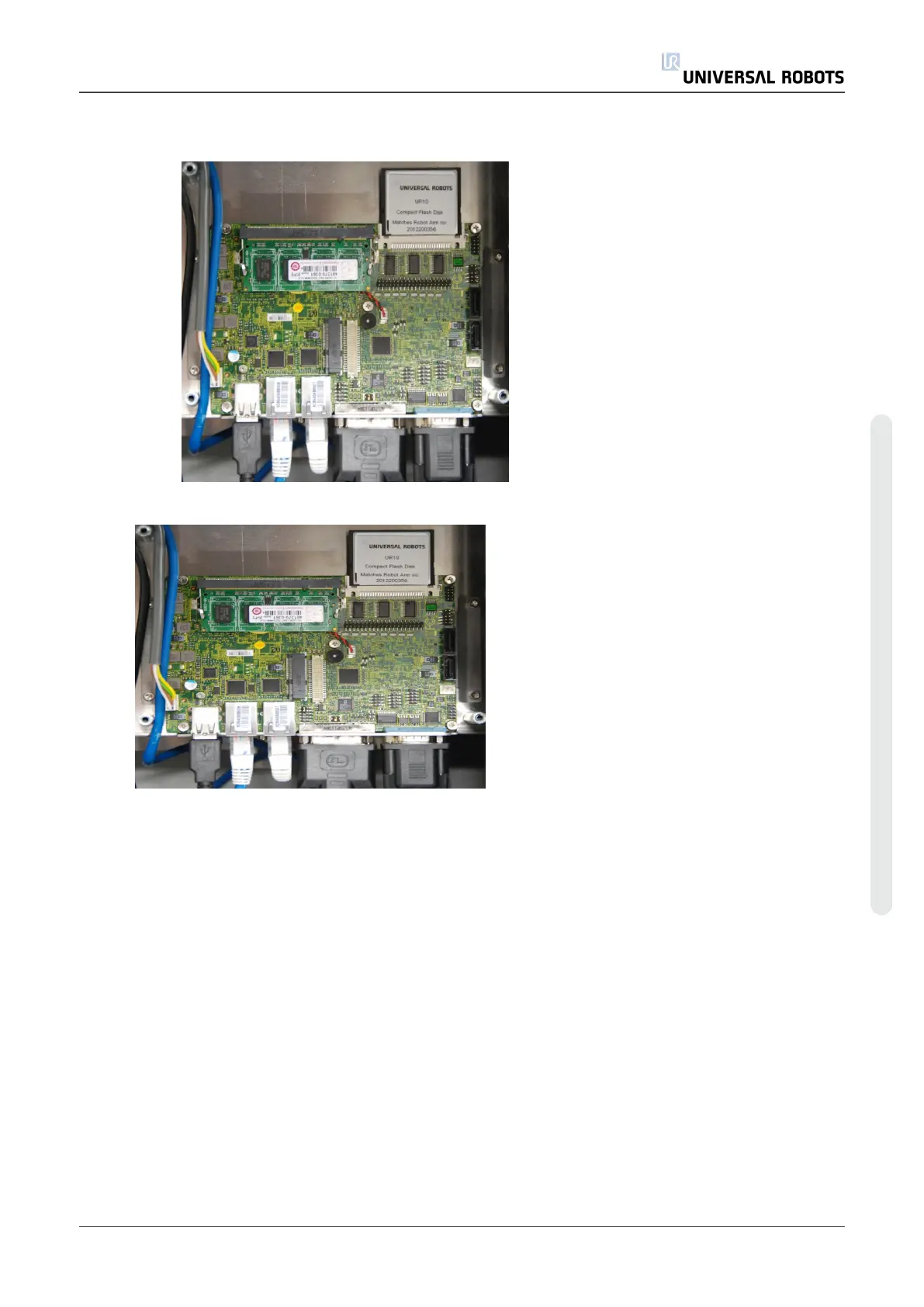
6. Replace Motherboard and tighten the 4 screws gently
7. Insert the 6 cables in correct positions. Special attention on the Ethernet cable to the
Safety Control Board. It must be connected to the right connector on the mother board
8. Re-install flash card and RAM block
9. Carefully put back the aluminum cover plate, make sure to mount it correct and fix it with
the 3 screws
10. Connect power and verify that teach pendant functions correctly.
5.3.2. Replacement of Motherboard 3.1
Replace Motherboard
Service Manual 55 UR5
5.Service and Replacement of parts
Copyright © 2009–2021 by UniversalRobotsA/S. All rights reserved.