2. Remove the bracket (foot of the controller box) that holds the cable inlet and pull out the
cables and plugs through this hole.
3. To install new teach pendant, thread cables through inlet, plug connectors into correct
positions, then mount aluminum cover into place.
4. Connect power and verify that teach pendant functions correctly.
See diagram: Schematic overview
Merge Control Box
WARNING
Before replacing ANY components inside the control box, it is IMPORTANT to do
a complete shutdown.
Follow the first 3 steps in section 5.3.7 Complete rebooting sequence.
When completing the following replacement, please follow the guidelines laid out in section
Handling ESD-sensitive parts
NOTE
Use the same procedure for power down and removing the aluminum cover plates
as in chapter, Replacement of Motherboard 3.0, Replacement of Motherboard 3.1
or Replacement of Safety Control Board
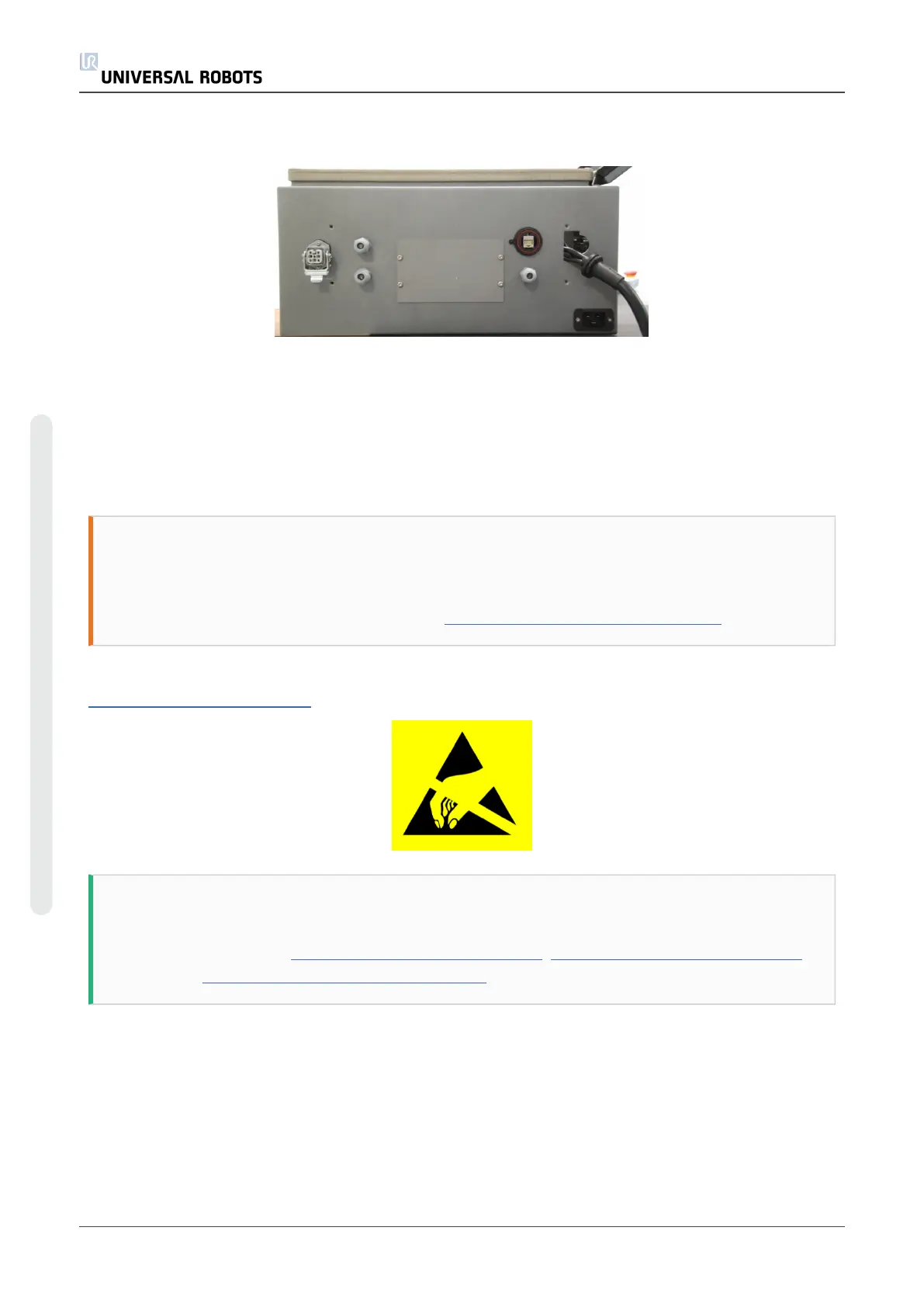
1. Disconnect 4 cables:
1. Red plug with black cable
2. Black DVI cable
3. Black USB cable
4. Black cable for RS232-connection to touchscreen
UR5 68 Service Manual
5.Service and Replacement of parts
Copyright © 2009–2021 by UniversalRobotsA/S. All rights reserved.