10 l Smatrix Pulse | Installation and Operation Manual
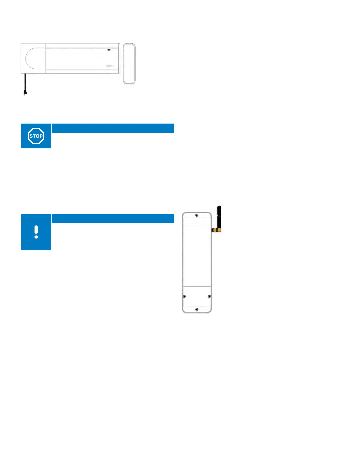
A380265A Controller (X-265)
with Antenna (A-265)
Warning!
Per Table 3-1, use Uponor 24V actuators to ensure
compatibility with the Controller.
The Controller operates the actuators, which, in turn,
affect the flow of the supply water to change the
indoor temperature using information transmitted from
registered thermostats and system parameters.
The Controller, which is typically located near the system
manifolds, operates up to six (6) thermostats and eight
(8) actuators.
Note
If using remote access to view and adjust
room temperatures along with other smart
home settings, the system must include one
Communication Module.
Main Features
• Integrated Dynamic Energy Management functions, such
as autobalancing (on by default)
• Electronic control of 24V actuators
• Connects up to eight (8) actuators
• Two-way communication with up to six (6) thermostats
• Heating outputs for Boiler and Pump operation
• General purpose input (GPI) for heating/cooling switch
over
• Valve and pump exercise
• Control of combined underfloor heating and cooling
• ECO mode provides lower indoor temperature in heating
mode and increased indoor temperature in cooling
mode; activated in all rooms at once using a dry contact
• Communication distances up to 98 ft. (30 m) away from
the controller when used as a sub-Controller
• 115V plug-in power cord (42")
Options
• Increase Controller functionality by adding an Expansion
Module that adds six (6) additional thermostats and six
(6) additional actuators
• Other functions such as comfort setting, room bypass,
and supply temperature monitoring requires (requires
Communication Module and Smatrix Pulse App)
• Modular placement (detachable Transformer)
• Free placement and orientation when installing the
controller (except the antenna; must be mounted
vertical)
• Heating/cooling outputs, and/or Comfort/ECO mode
switched by dry contact or Smatrix Pulse App (requires
Communication Module)
Included Components
• Controller with Antenna (part number A380265A)
• Power supply/Transformer (part number A3850050)
• DIN rail
• Mounting hardware
• End cap
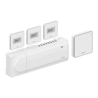
A3801263 Relay Module (M-263)
Figure 3-6: A380265A Controller
(X-265) with Antenna (A-265)
Figure 3-7:
A3801263 Relay
Module (M-263)
The Relay Module adds two extra
output relays to the system.
These can be setup in different
combinations to control heating and
cooling operation.
The Relay Module can also be paired
with a thermostat to control a fan
coil or furnace and air-conditioning
combination, along with fan
operation. This application uses three
(3) relays.
Main Features
• Dry contacts (24 VAC, 5 A)
• Pump control and heating/cooling
output function
• Other combinations are available,
but require Communication Module
and Smatrix Pulse App
• Communication distances up to
98 ft. (30 m) away from Controller