uponor.com l 29
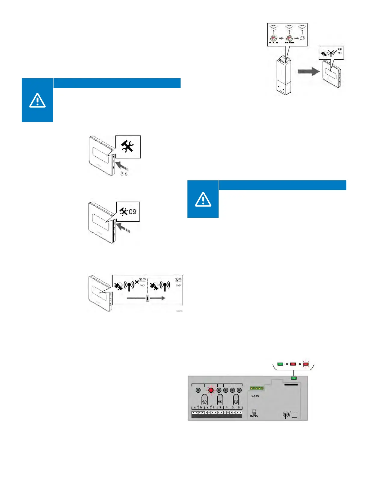
Use the following steps to link a thermostat to a Relay
Module:
• Ensure the Relay Module is powered up and the LED is on.
• Activate the registration mode on the Relay Module by
pressing the button for three (3) seconds. When done
correctly, the linking LED will begin to slow flash red.
Caution!
If no button on the thermostat is pressed for about
eight (8) seconds, while in a sub menu, the current
values will be saved, and the software exits to the
Settings Menu. After 60 seconds, the Relay Module
will return to normal run mode.
• Enter the
configuration
mode on the
Digital Thermostat
by pressing and
holding the middle
button for about
three (3) seconds.
• Once the menu is
activated, press the
up (or top) button
until 09 is shown in
the top right corner.
• Press the middle
button and a line will
appear under 09.
• Press the top
button until “CNF”
is displayed in the
screen.
• Once successfully paired,
the LED will flash quickly
on the relay and a
check will appear on the
thermostat screen.
• Press the OK (middle)
button to confirm the
change.
• Exit the Settings Menu by
pressing and holding the
OK button for three (3)
seconds.
Linking a Relay Module to a Controller
A Relay Module can directly link to a Controller. Each
Controller can only have one Relay Module linked to it to
mirror or duplicate the pump and boiler outputs. This can
be useful in installations when getting wiring back to the
mechanical room for a zone pump and/or boiler is an
issue in retrofit or remodel applications.
Caution!
When linking a Relay Module to a Controller
and using the “second layer” of pairing, other
Controllers will pair to Channel 1 and the Relay
Module will pair to Channel 2.
Use the following steps to link or register a Relay Module to
a Controller:
• Enter the pairing mode. Press and hold the OK button on
the Controller until the LED for the first available channel
begins to flash Red.
• Using the < or > buttons, move the flashing LED from the
channels to the power LED on the Controller. The LED will
begin to flash red. This secondary layer is for linking Relay
Modules and other controls to Controllers.
• Press the OK button and the LED for Channel 1 will begin
to flash red.
• If done correctly, the LED for Channel 1 will begin to flash
red and the power LED will start flashing in a pattern (long
flash, short unlit flash, long flash, etc.).
• Press the > button to move the flashing red LED to
Channel 2.
Figure 7-5: Press and hold middle
button for three (3) seconds
Figure 7-6: Press top
button until 09 is shown
in right top corner
Figure 7-7: Press top button until
CNF displays on the screen
Figure 7-9: Enter pairing mode
Figure 7-8: Successful pairing