30 l Smatrix Pulse | Installation and Operation Manual
Note
The Relay Module will only link to Channel 2 on
Controllers.
• Select (or lock) the channel by pressing the OK button.
The LED should begin to flash green.
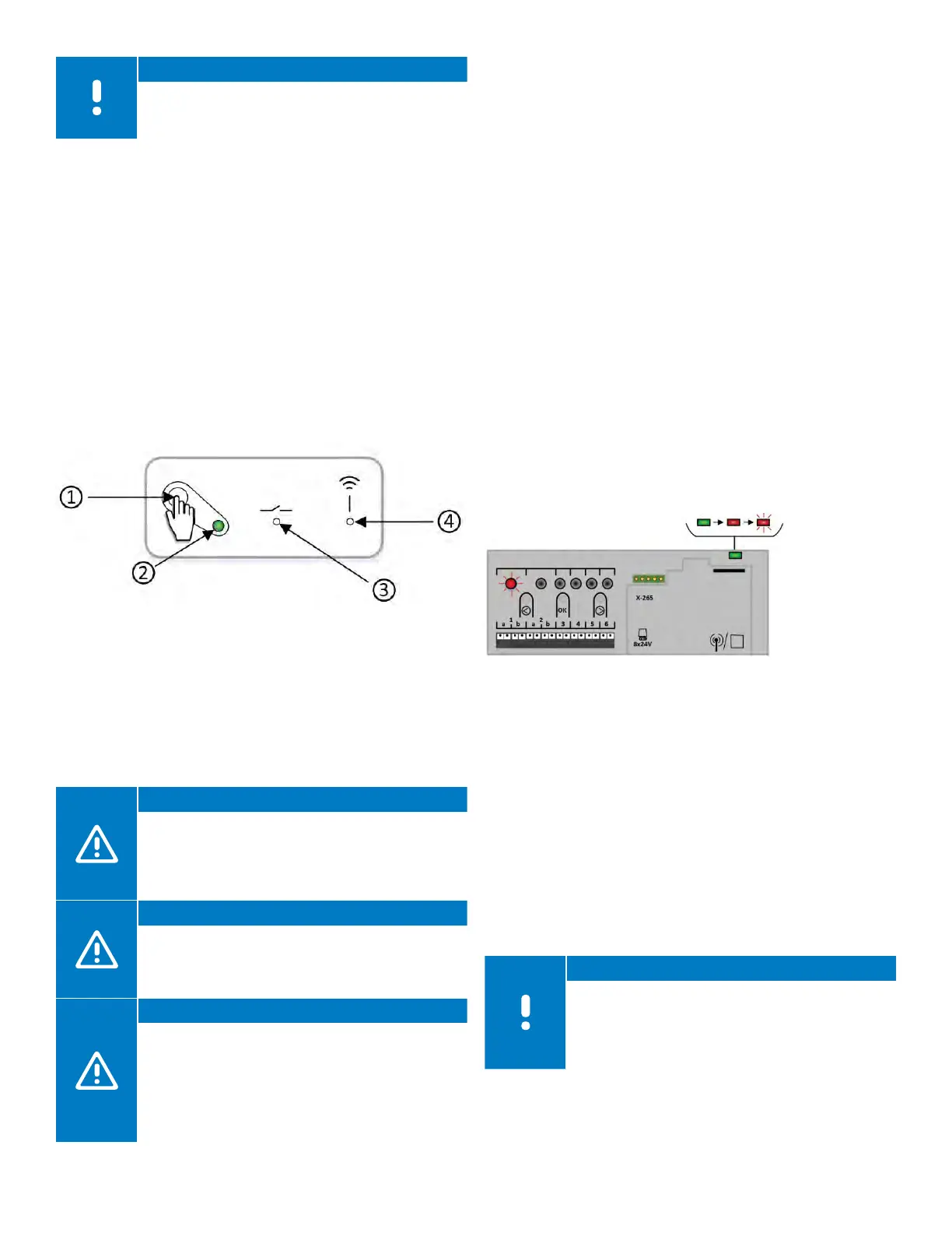
• Make sure the Relay Module is powered up and the power
LED (2) is on solid green.
• Activate the registration mode on the Relay Module by
pressing the registration button (1) for three (3) seconds.
When done correctly, the link LED (4) will begin to slow
flash red.
• The link LED (4) on the Relay Module will begin to
begin flashing faster, and the LED for Channel 2 on the
Controller will turn to solid green. At this time, the Relay
Module is paired with the Controller.
• Press and hold the OK button to exit pairing mode. When
done correctly, the power LED will be solid green.
Linking a Controller to a Sub-Controller
When multiple Controllers are installed in a system, only
one can be connected to a Communication Module.
This unit is considered the Primary Controller. All other
Controllers will connect to Antennas and are considered
sub-Controllers.
Caution!
For thermostat information to appear on the
Smatrix Pulse App or for Over The Air (OTA)
updates to be installed and updated, all sub-
Controllers will need to be linked to the Primary
Controller.
Caution!
The Controller will time out after about 10 minutes
of inactivity and revert to normal operation. The
timer will be reset when a button is pressed or if a
device has been Registered.
Caution!
If a Controller has been connected to a
Communication Module, disconnect the
Communication Module, and restore it to the
sub-Controller state by performing a factory reset.
Existing sub-Controllers in the system must then
either reset system device Channel 01 or register to
another Primary Controller.
To link a sub-Controller to a Primary Controller, use the
following steps:
• Enter the pairing mode on the Primary Controller (one
connected to the Communication Module). Press and
hold the OK button on the Controller until the LED for the
first available channel begins to flash red.
• Using the < or > buttons, move the flashing LED from the
channels to the power LED on the Controller and it will
begin to flash red.
• Press the OK button.
• If done correctly, the LED for Channel 1 will begin to flash
red, and the power LED will start flashing in a pattern
(long flash, short flash, long flash, etc.).
• Repeat the steps for the sub-Controller to be paired with
Primary Controller.
• Enter the pairing mode on the sub-Controller. Press and
hold the OK button on the Controller until the LED for the
first available channel begins to flash red.
• Using the < or > buttons, move the flashing LED from the
channels to the power LED on the Controller, and it will
begin to flash red.
• Press the OK button.
• If done correctly, the LED for Channel 1 will begin to flash
red, and the power LED will start flashing in a pattern
(long flash, short flash, long flash, etc.).
• Select Channel 1 and press OK to lock in the channel.
• Channel 1 LED on both the sub-Controllers turns solid
green and the registration is complete. Channel 1 LED on
the Primary Controller will continue to flash as additional
sub-Controllers can be paired during this time.
• Exit the pairing mode by pressing OK for three (3)
seconds on both controllers.
Note
The next sub-Controller can be registered within
10 minutes without the need to activate Channel 1
on the Primary Controller again. If the registration
times out, the process can begin again without
overwriting existing sub-Controller registrations.
Figure 7-11: Pair a sub-Controller to
a Primary Controller
Figure 7-10: Relay Module status items