uponor.com l 37
Menu 05: High Floor Temperature Limitation
Default: 78°F (26°C)
Setting range: 38 – 95°F (20 – 35°C), 1°F (0.5°C) increments
Note
This parameter cannot be set lower than the set
value in settings Menu 06 (low floor temperature
limitation).
In this menu, a limit on the highest allowable floor
temperature is set. This menu is only visible if control
mode RFT is activated in Menu 04. For systems with a
Communication Module, this menu only shows the set
value. Changes are done in the Smatrix Pulse App.
Menu 06: Low Floor Temperature Limitation
Default: 68°F (20°C)
Setting range: 50 - 86°F (10 – 30°C), 1°F (0.5°C) increments
Note
This parameter cannot be set higher than the set
value in settings Menu 05 High floor temperature
limitation.
In this menu a limit on the lowest allowable floor
temperature is set. This menu is only visible if control
mode RFT is activated in Menu 04. For systems with a
Communication Module, this menu only shows the set
value. Changes are done in the Smatrix Pulse App.
Menu 07: Cooling Allowed
This menu sets whether a room will receive cooling or not.
This menu is not visible if a Communication Module is
connected to the system. The setting is then available in
the Smatrix Pulse App.
Menu 08: Display Units
This menu sets the temperature information in °F or °C.
Menu 09: Relay Module Integration
Use this menu to link a thermostat to a Relay Module for
controlling a forced-air heating and cooling system or fan
coil unit.
Menu 11: Room Temperature Calibration
Default: 0.0
Setting range: -6.0 – 6.0, 0.1 increments
This menu adjusts the temperature in the display if there
is a difference between the displayed versus the actual
temperature.
Menu 12: Invert Screen
This menu inverts the color in the display. The background
is black, and the numbers and icons are white.
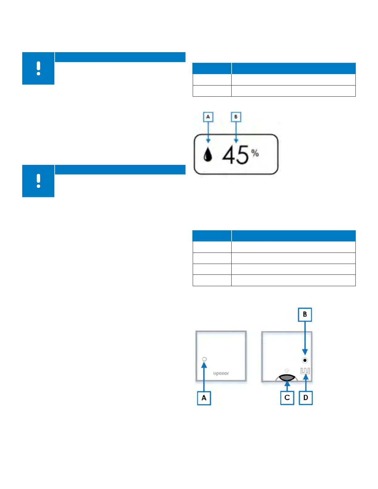
Relative Humidity
The Digital Thermostat (T-169) also displays the relative
humidity level in the room or space. Pressing the OK button
three (3) times will display the following information:
Reference Description
A Relative humidity
B Relative humidity reading
Table 9-10: Relative humidity displays
Mini Sensor (T-161) Operation
During normal operation, the thermostat settings and
control is performed via the Uponor Smatrix App (requires
the Communication Module).
Reference Description
A Status LED
B Registration button
C Battery CR
D 2032V terminals for external sensor
Table 9-11: Mini Sensor (T-161) components
Figure 9-7: Relative Humidity
Figure 9-8: Mini Sensor (T-161) operation