Schematics
Section
6-9AB38 Work Platform
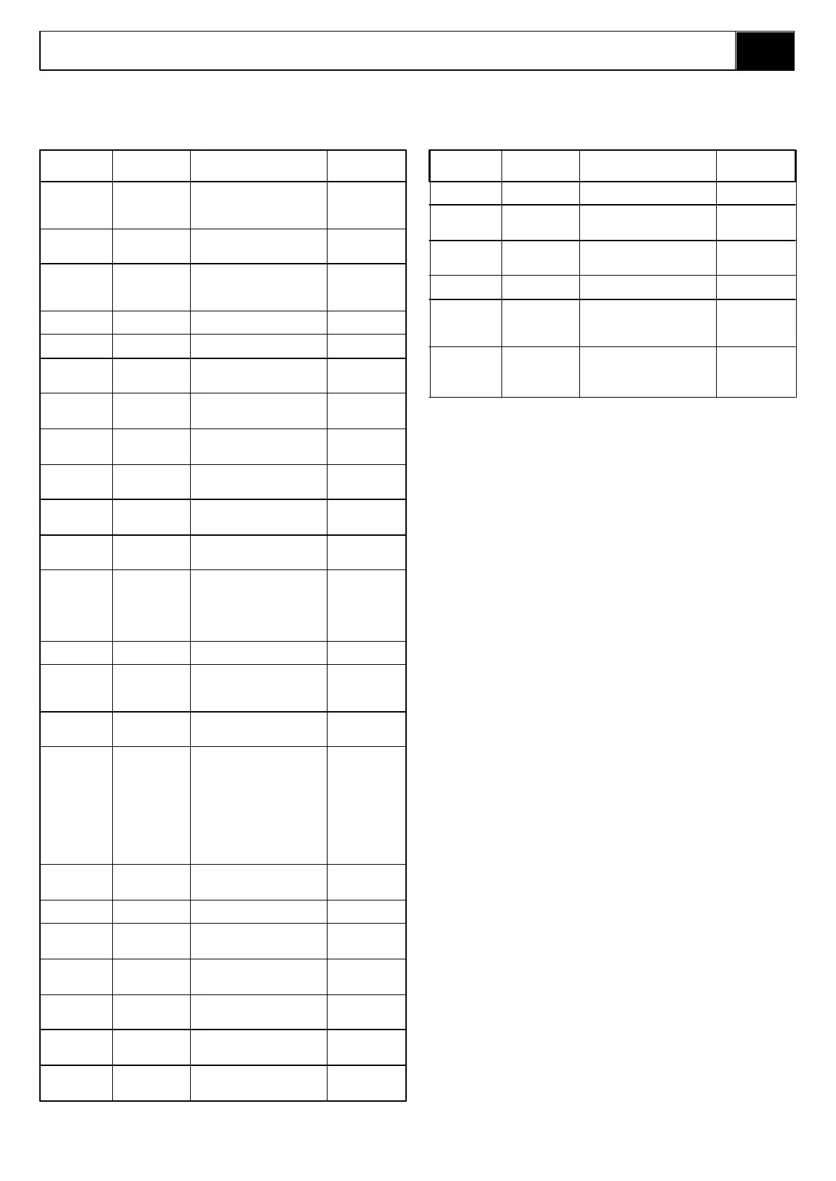
REFERENCE NAME FUNCTION LOCATION
V10 (RV) Main relief Sets max system pressure to On main
valve. 145 Bar manifold block.
V11 Single Prevents back flow and On base of
Overcentre provides a hydraulic lock on upper, lower &
valve. the cylinder. tele cylinders.
V12 Emergency Allows upper and lower boom On base of
lowering valve. to be manually lowered. upper and lower
cylinders.
V13 Pilot operated Holds tele cylinder in position On base of
check valve. after controls are released tele cylinder.
V14 Dual Holds pressure in On base of
Overcentre master/slave closed circuit master cylinder.
valve. and provides host burst
protection. (Set 160 Bar).
V15 Dual Holds pressure in slave On base of
Overcentre cylinder and provides host slave cylinder.
valve. burst protection.
(Set 120 Bar).
6.2
6.2. Hydraulic Schematics
Table 6-2: Hydraulic Schematic Legend
REFERENCE NAME FUNCTION LOCATION
BRK Brake. Spring applied - hydraulically On front end of
released brakes to stop wheel drive
rotation of drive wheels. motors on
(Set at 100 Bar). chassis.
CLRV Cross-line To limit the max. operating On main
relief valve. pressure of the slew motor. manifold block.
(Set at 50 Bar).
CV Check Valve. To prevent oil pressure in the On main
brake line from being lost manifold block.
through the main pressure
line.
CYL1 Lower boom lift Provides the force to lift the Foward of first
cylinder. lower boom - Boom1. post
CYL2 Upper boom lift Provide the force to lift the Behind second
cylinder. upper boom - Boom2. post
CYL3 Tlelscopic Provides the force to Inside Boom2
cylinder. push/pull the tele-boom & Tele boom.
- Boom3.
CYL4 Steering Provides the force to Inside front of
cylinder. push/pull the steering torque chassis.
arms.
CYL5 Master levelling Provides the pressure to the Behind the
cylinder. slave cylinder for cage second post
levelling.
CYL6 Slave levelling Provides the force to level Close to cage
cylinder. the cage up/down. pivot at inner
Tele boom.
FL1 Return line Continuously filters hydraulic On top of the
filter. return oil. hydraulic
(10 Micron) reservoir.
HP Handpump. Used for retraction of tele On side of
boom in the case of power manifold block.
failure. Delivers 15cc/stroke.
MMB Main manifold Contains the directional On hydraulic
block. control valves and relief reservoir in
valves that distribute oil to chassis.
the various functions and
control the operating
pressures.
MOT1 Slew Motor. Drives slew bearings drive Connected to
pinion. drive pinion.
MP Motor/Pump Gear pump close coupled to On chassis.
set. D.C electric motor. Provides
pressurised oil flow for all
hydraulic functions.
V1 Brake oil This valve is energised to On main
supply valve. allow oil into the brake manifold block
release chamber.
V2 Brake valve. When energised this valve On main
prevents the pressurised manifold block.
brake oil from venting back
to tank. When the machine is
stationary this valve
de-energises and the brake
oil vents to tank and the
brake springs apply
themselves and keep the
machine stationary.
V3 Pressure Prevents pressures in On main
reduction valve. excess of 100 Bar entering manifold block.
the brake chambers.
V4 Slew Directional Send oil to the left or right On main
Control Valve. side of the slew motor. manifold block.
V5 Steer Send oil to the annular or full- On main
Directional bore side of the steering manifold block.
Control Valve. cylinder.
V6 Tele Send oil to the annular or full- On main
Directional bore side of the telescopic manifold block.
Control Valve. cylinder.
V7 Boom2 Send oil to the annular or full- On main
Directional bore side of the Boom2 manifold block.
Control Valve. cylinder.
V8 Boom1 Send oil to the annular or full- On main
Directional bore side of the Boom1 manifold block.
Control Valve. cylinder.
V9 Levelling Send oil to the annular or full- On main
Directional bore side of the levelling manifold block.
Control Valve. cylinders.
Notes:
1. All of the Overcentre Valves represented within
this schematic have a 5:1 Pilot Ratio.
2. The P/O Check Valve represented has a 3:1
Pilot Ratio.
3. The maximum flow rate of the Pump/Motor Unit
is limited to 15 L/min @ 100% speed. Although
it should be noted that the actual flow rate will
depend on the applied load and the D.C. Motor
speed.
4. The maximum ‘Return’ flow rates for each of
the functions are restricted to the following
values;
l Slew... 4 L/min
l Boom1... 8 L/min
l Boom2... 5 L/min
l Tele... 5 L/min
l Steering... 6 L/min.
 Loading...


