1
vacon • 10 General information
Local contacts: http://drives.danfoss.com/danfoss-drives/local-contacts/
1.6 Type identification number
NOTE: This information is relevant only for special applications designers using the VACON
®
NC1131-3 engineering tool.
Each VACON
®
OPTxx board has a unique type designation code. Besides the type designation code,
each board has a unique Type identification number which is used by the system program to identify
which board is plugged into which board slot. The system program and the application use the Type
ID also to establish the needed connections in order to achieve the desired functionality of the
available I/O boards in the control unit. The ID code is loaded in the memory of the board.
1.7 Defining functions to inputs and outputs
How to connect functions and the available I/O depends on the application you use. The VACON
®
All
in One Application Package includes seven applications: Basic Application, Standard Application,
PID Control Application, Multi-Step Speed Control Application, Local/Remote Control Application,
Pump and Fan Control Application with Autochange and Multipurpose Control Application (see All-
in-One Application Manual). All but two applications of these use the conventional VACON
®
method
to connect functions and the I/O. In the Function to Terminal Programming Method (FTT), you have
a fixed input or output that you define a certain function for. The mentioned two applications, Pump
and Fan Control and Multipurpose Control Application, however, use the Terminal to Function
Programming Method (TTF) in which the programming process is carried out the other way round:
Functions appear as parameters which the operator defines a certain input/output for.
Connecting a certain input or output to a certain function (parameter) is done by giving the
parameter an appropriate value, the address code. The code is formed of the Board slot on the
VACON
®
NX control board (see page 2 and 3) and the respective input/output number. See below.
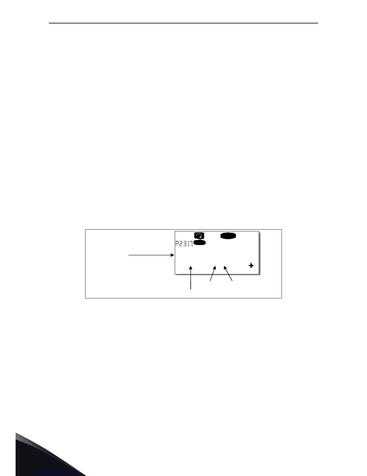
Example: You use the Pump and Fan Control Application. You want to connect the digital output
function Reference fault/warning (parameter 2.3.1.7) to the digital output DO1 on the basic board
OPTA1.
First find the parameter 2.3.1.7 on the keypad. Press the Menu button right once to enter the edit
mode. On the value line, you will see the terminal type on the left (DigIN, DigOUT, An.IN, An.OUT)
and on the right, the present input/output the function is connected to (B.3, A.2 etc.), or if not
connected, a code 0.#.
When the value is blinking, hold down the Browser button up or down to find the desired board slot
and input/output number. The program will scroll the board slots starting from 0 and proceeding
from A to E and the I/O numbers from 1 to 10.

 Loading...


