0020308121_04 Installation and maintenance instructions 11
Information Meaning
PMS Permissible operating pressure, heating
mode
Pnw Maximum output power
PMW Permissible operating pressure for do-
mestic hot water mode
D Specific domestic hot water flow rate
value
DSN Device specific number
NOx-class NOx class (nitrogen oxide emissions)
T
max
Maximum flow temperature
V Mains voltage
Hz Mains frequency
W Maximum electrical power consumption
IP IP rating
Heating mode
DHW mode
P
n
Nominal heat output range (80/60 °C)
P
nc
Condensing nominal heat output range
(50/30 °C)
Q
n
Heat input range
Q
nw
Heat input range for domestic hot water
generation
Barcode with serial number
3rd to 6th digits = production date
(year/week)
7th to 16th digit = product article number
5.6 Serial number
The serial numbers are located on the underside of the front
panel and on the data plate.
5.7 Sitherm Pro™ technology
The intelligent combustion regulation is based on the adapt-
ive Siemens Sitherm Pro™ combustion optimisation.
5.8 Display of the energy consumption, energy
yields and efficiencies
Note
When replacing the PCB, the values recorded up
to that point are completely reset in the product
and system control.
The product, the system control and the app show approx-
imate values for energy consumption, energy yields and ef-
ficiencies, which are extrapolated based on calculation al-
gorithms.
The values that are displayed in the app may differ from the
other display options due to staggered transfer intervals.
The determined values depend on:
– Installation and system of the heating installation
– User behaviour
– Seasonal weather effects
– Various tolerances of unit-internal components
The values can be read in the following time forms:
– Today
– Yesterday
– Last month
– Last year
– Total
The recording of the values only includes the product in the
factory-delivered condition. Supplementary accessories,
even if they are installed on the product, as well as any other
components in the heating system and other external con-
sumers, are not part of the data recording.
Deviations between the determined values and the actual
values may be significant. The determined values are there-
fore not suitable for creating or comparing energy billing, for
example.
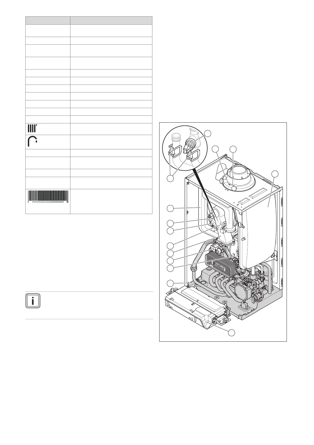
5.9 Product design
1 Connection for the
air/flue pipe
2 Flue gas analysis point
3 Expansion vessel
4 Electronics box
5 Hydraulic block
6 Fan
7 Gas valve assembly
8 Compact thermal
module
9 Control electrode
10 Heat exchanger
11 Ignition electrode
12 Air intake pipe
13 Temperature sensor
14 Water pressure sensor
 Loading...


