58 Installation and maintenance instructions 0020308121_04
1. Open the electronics box. (→ Section 7.10.3)
2. Replace the PCB in accordance with the set-up and
installation instructions supplied.
3. Close the electronics box. (→ Section 7.10.4)
4. Establish the power supply.
◁ The DSN code is transferred from the display to
the PCB.
13.7.15 Replacing the PCB and the display
Note
Spare parts must only be used once.
After replacing the display and PCB assemblies,
all of the installation-specific settings are deleted.
If required, use the installation-specific settings
from the "Diagnostics codes" table in the appendix
if they have been noted there. (→ Appendix D)
xxxxxxxxxx
xxxxxx
xxxxxxxx
xxx
xxxxxx
xxxxxxxxxx
xxxxxx
xxxxxxxx
xxxxx
xxxxxx
xxxxxxxxxx
xxxxxx
xxxxxxxx
xxx
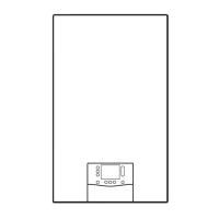
1. Read the offset (1) that is printed on the rear (type A)
or underside (type B) of the gas valve assembly and
note this down. Use a mirror, for example.
2.
Gas-Wandheizgerät mit Brennwerttechnik
Vaillant GmbH
Berghauser Str. 40 42859 Remscheid, Germany
DSN: XXX
as-Wandheizgerät mit Brennwerttechni
Read the DSN-Code (Device Specific Number) from
the data plate on the rear of the electronics box and
note this down.
3. Open the electronics box. (→ Section 7.10.3)
4. Replace the PCB and display according to the set-up
and installation instructions supplied; this is best done
one after the other. Doing so in this way means that
the old PCB can transfer the saved values to the new
display or, alternatively, the old display can transfer the
saved values to the new PCB.
5. Close the electronics box. (→ Section 7.10.4)
6. Replace the control electrode. (→ Section 13.7.18)
7. Install the front casing. (→ Section 7.11)
8. Establish the power supply.
9. ◁ After switching on, the product switches directly to
the menu to select the language.
10. Select the required language.
11. Set the read-off value DSN code (via D.093) for the
product type. (→ Section 8.3)
◁ The electronics are now set to the product type and
the parameters of all diagnostics codes are set to
factory settings.
◁ The installation assistant starts.
12. If the gas valve assembly offset that you read has five
digits, set diagnostics code D.052 using the first three
digits. (→ Section 8.3)
13. If the gas valve assembly offset that you read has three
digits, set diagnostics code D.052. (→ Section 8.3)
14. If the product is set with liquefied petroleum gas as the
gas type and the gas valve assembly offset that you
read has five digits, set diagnostics code D.182 using
the last two digits. (→ Section 8.3)
15. Check the installation-specific settings and adjust
these.
16. Start the test operation in chimney sweep mode by
pressing .
13.7.16 Replacing the PCB on the shift-load cylinder
1. Comply with the set-up and installation instructions
provided with the spare parts.
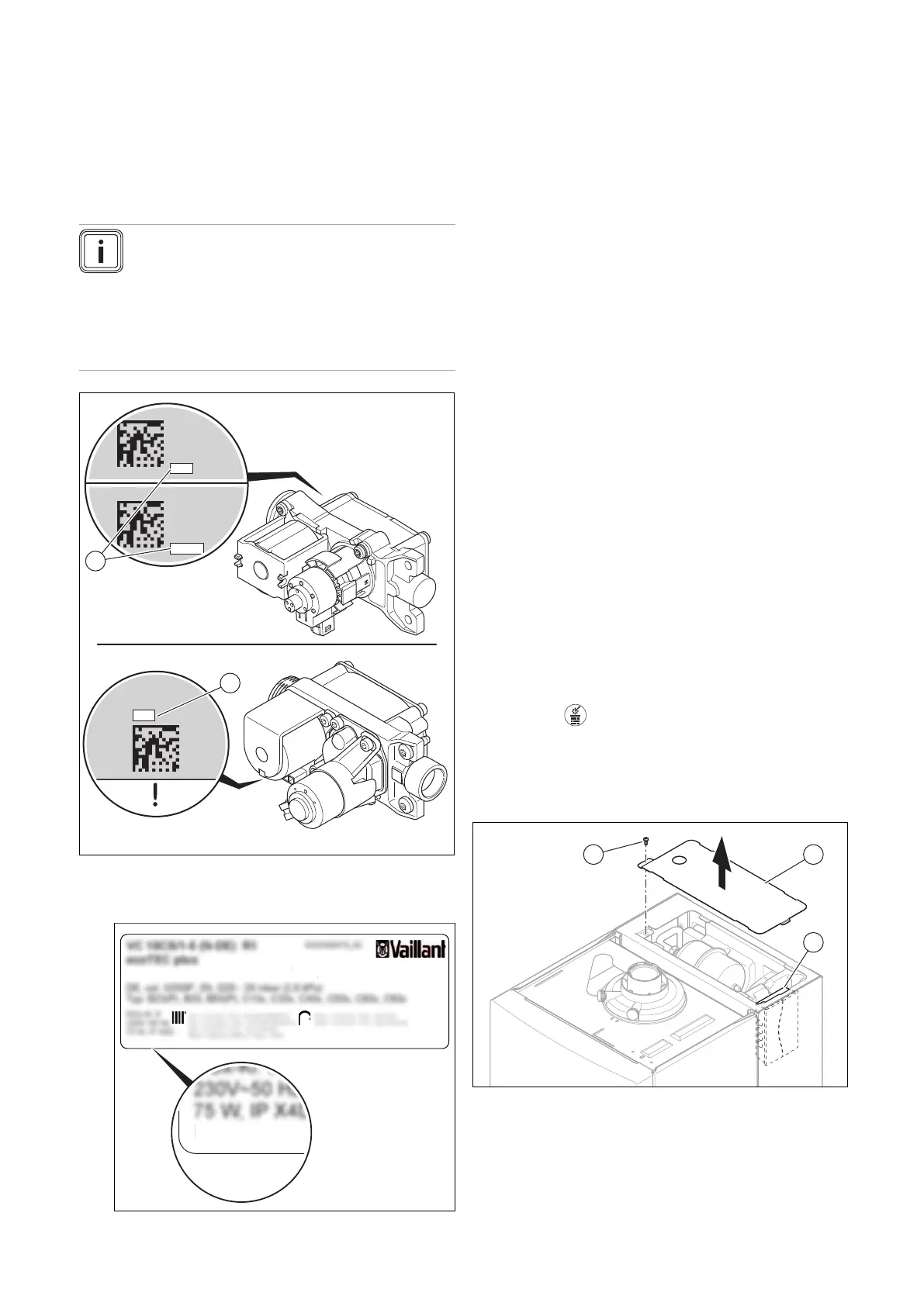
2. Unscrew the screw (1) from the cover of the shift-load
cylinder and remove the cover (2).
3. Remove the electronics box with the shift-load cylin-
der's PCB (3) from the appliance slot.
4. Open the electronics box and remove the plug from the
PCB.
 Loading...


