0020308121_04 Installation and maintenance instructions 29
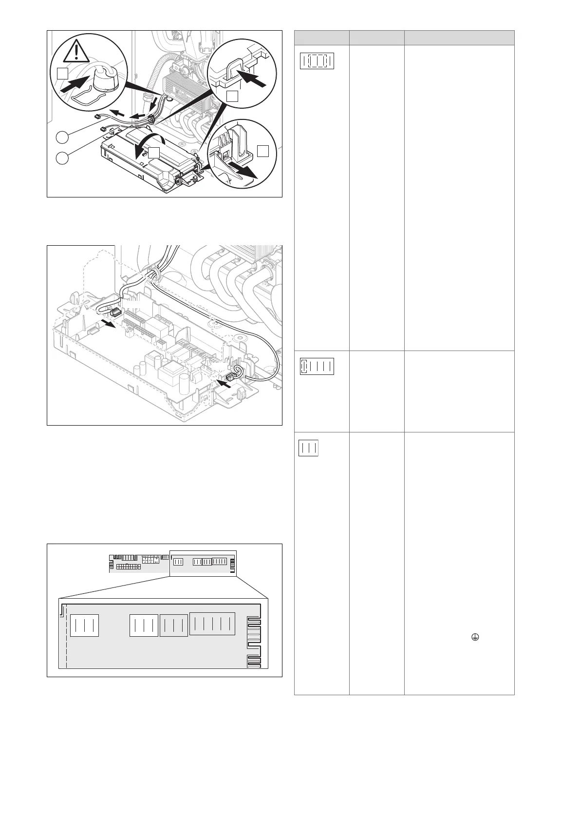
6. Guide the pump cable (2) with plug X12 along the out-
side of the electronics box.
7. Guide the sensor cable (1) with plug X31 to the PCB.
8. Plug the pump cable's X12 plug into slot X12 (right-
hand side of the PCB).
9. Plug the plug X31 for the actoSTOR module's control
cable into slot X31 (left-hand side of the PCB).
10. Secure the cables over the cable terminals in the elec-
tronics box.
7.10.8 Connection options on the product
230 V connection area
X12b
X1
CH Pump
RT 230V Mains
X19
X41X36
X100
Opt 1
X16
Fan
X11
X24
X20
2a X12b
X1
CH Pump
RT 230V Mains
X19
Opt 1
X16
Fan
X11
– 230 V power supply
– Optional relay on the PCB
– 230 V room thermostat
Slot Item Function
X1 main power supply 230 V
input
Caution.
Risk of material damage due
to high connected voltage.
At mains voltages greater
than 253 V, electronic com-
ponents may be damaged.
► Ensure that the mains
voltage is 230 V
► Provide one common
power supply for the boiler
and for the corresponding
control:
– Power supply: Single-
phase, 230 V, 50 Hz
– Fuse protection: ≤ 3 A
► For the power supply
cable, use a flexible three-
core cable that complies
with the relevant standards,
which is routed through the
cable duct into the product.
► Connect the product us-
ing a fixed connection and
an electrical partition with
a contact gap of at least
3 mm (e.g. fuses or power
switches).
X1 230 V room thermostat
control
► Connect the switched live
supply of your 230 V RT to
the RT marked X1 position
(besides LNPE). Do NOT
connect the 230 V to any
other terminal, e.g. X100.
X16 Optional relay (230 V)
With diagnostic point D.026
you can use one function of
10 possible.
1. External pump/ 2. Circula-
tion pump/ 3. Solar cylinder
bypass valve/ 4. Anti-legion-
ella pump/ 5. eBUS remote
control/ 6. Solar pump/ 7.
External fault message/ 8.
External solenoid valve/ 9.
Extraction hood/ 10. Cylinder
charging pump
Note
An accessory is available in
order to use two additional
functions out of these ten
potential functions.
► Connect the connection
cable for the external button
to the terminals 1 0 and
6 (FB) on the X41 edge
connector, which is included
with the control.
► Plug the edge connector
into PCB slot X41.
 Loading...


