0020308121_04 Installation and maintenance instructions 17
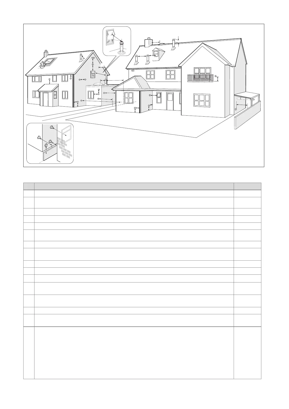
7.2.3 Position of the air/flue terminal
J
J
N
Q
S
S
P
U
B
Boundary
G
D
J
J
R
V
M
T
G
C
W
E
F
L
A
K
S
P
S
F
X
A
Y
Boundary
Z
H
Aa
S
Z
Ba
7.2.3.1 Positioning the terminal of a fan-supported flue system
Installation site Dimensions
A
Adjacent to a boundary. 300 mm
B
1)
The dimension below eaves, balconies and car ports can be reduced to this value, as long as the flue terminal is
extended to clear any overhang. External flue joints must be sealed with a suitable silicon sealant.
25 mm
C Between a vertical flue terminal and a window or dormer window on a roof. 1,500 mm
D Between terminals facing each other. 1,200 mm
E Vertical flue clearance, adjacent to a boundary line. 300 mm
F
2)
Distance to a boundary line, unless it will cause a nuisance. BS 5440:Part 1 recommends that care is taken
when siting terminal in relation to boundary lines.
600 mm
G Minimum clearance from a skylight to a vertical flue or to another vertical flue. Min. 300 mm
H
Vertical flue clearance, to noncombustible building material.
Vertical flue clearance to combustible building material.
500 mm
1,500 mm
J Above, below and either side of an opening door, air vent or opening window. 300 mm
K Diagonally to an opening door, air vent or opening window. 600 mm
L
2)
To an internal or external corner. This dimension can be reduced if a plume diverter is used. 200 mm
M
Below a Velux window.
Above or to either side of the Velux window.
2,000 mm
600 mm
N
From a pitched roof.
In regions with heavy snowfall.
400 mm
500 mm
P From vertical drain pipes and soil pipes. 25 mm
Q
Below eaves.
Below gutters, pipe and drains.
200 mm
75 mm
1) There should be no ventilation/opening in the eaves within 300 mm distance of the terminal.
2) These dimensions comply with the building regulations, but they may need to be increased to avoid wall
staining and nuisance from pluming depending on site conditions.
– Terminals must be positioned so to avoid combustion products entering the building.
– Support the flue at approximately one metre intervals and at a change of direction, use suitable brackets and
fixings.
– Installations in car ports are not recommended.
– The flue cannot be lower than 1 metre from the top of a lightwell due to the build up of combustion products.
– Dimensions from a flue terminal to a fanned air inlet to be determined by the ventilation equipment.
 Loading...


