60 Installation and maintenance instructions 0020308121_04
9. Open the gas stopcock.
10. Connect the product to the power supply.
11. Activate diagnostics code D.147 via D.146.
(→ Section 8.3)
12. Set diagnostics code D.147 to New electrode
(→ Section 8.3).
13. Check the O₂ content. (→ Section 9.13.4)
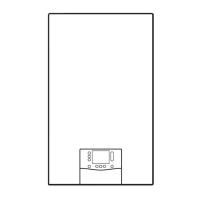
13.7.19 Routing wiring harnesses
Note
High temperatures may damage the wiring har-
nesses.
Incorrect routing of the wiring harnesses may lead
to electromagnetic faults.
To prevent damage and faults, install the wiring
harnesses as shown in the figure.
1 Hydraulics wiring har-
ness (impeller water
flow sensor, water pres-
sure sensor, temperat-
ure sensor, prioritising
diverter valve)
2 Wiring harness (fan,
gas valve assembly,
temperature sensors)
3 Ignition wiring harness
4 Wiring harness for
the shift-load cylinder
module
5 Cable for the domestic
hot water pump
6 High-efficiency pump
cable
7 Cable for the socket
8 Wiring harness for the
power supply cable
1. Install the wiring harnesses as shown in the figure.
2. When plugging in the plug, observe the colour coding.
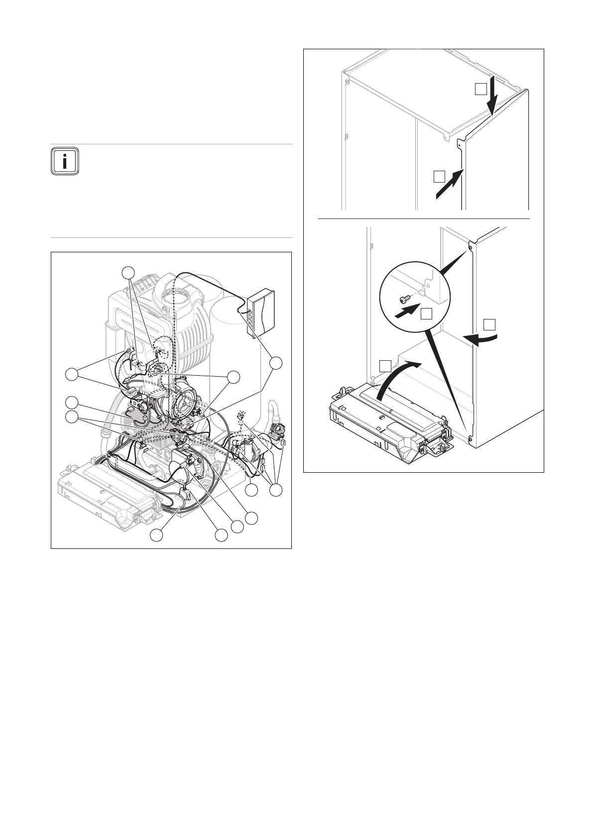
13.7.20 Completing repair work
1. If you have removed the side casing, install it as shown
in the figure.
2. Use two new screws to screw the side casing in tightly.
3. Open all service valves and the gas stopcock if this has
not yet been done.
4. Check the product for tightness. (→ Section 9.17)
5. Install the front casing. (→ Section 7.11)
6. If required, install the front panel below the display.
7. If required, install the modules below the product (→
Module installation instructions).
8. Establish the power supply if this has not yet been
done.
9. Switch the product back on if this has not yet been
done. (→ Section 9.4)
 Loading...


