20 Installation and maintenance instructions 0020308121_04
7.2.6 Replacing the standard connector for the
air/flue pipe, where required
7.2.6.1 Removing the standard connector for the
air/flue pipe
7.2.6.2 Installing the connector for the air/flue pipe,
60/100 mm or 80/125 mm diameter
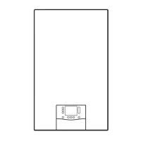
1. Remove the standard connector for the air/flue pipe.
(→ Section 7.2.6.1)
2. Insert the alternative connector. In doing so, pay atten-
tion to the latching lugs.
3. Turn the standard connector clockwise until it clicks
into position.
7.3 Installing the gas connection
▶ Install the gas pipe in accordance with the recognised
rules of technology.
▶ Remove the residues from the gas pipe by decoupling on
both sides and blowing through the gas pipe.
▶ Use the enclosed gas isolation valve. Observe the spe-
cified flow direction.
Note
Gas isolation valves with or without test nipple
are available in the dimensions 15 to 15 mm
or 22 to 15 mm.
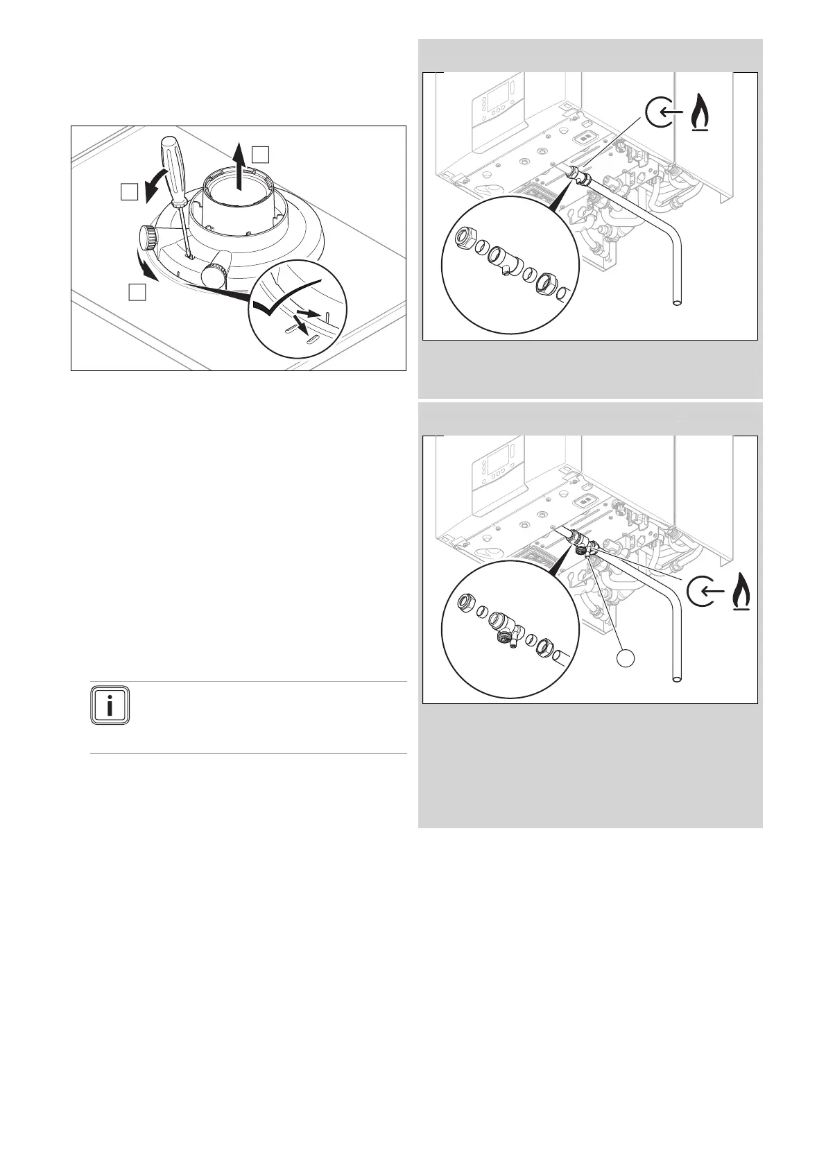
Condition: Gas isolation valve without test nipple
▶ Connect the product to the gas pipe as shown in accord-
ance with the recognised rules of good engineering prac-
tice.
Condition: Gas isolation valve with test nipple (requirement for BS 6891)
▶ Connect the product to the gas pipe as shown in accord-
ance with the recognised rules of good engineering prac-
tice.
▶ Always ensure that the test nipple (1) is sealed and is
correctly checked for tightness. Tightening torque, see
appendix.
– Working materials: 3 mm hex key
▶ Purge the gas pipe before start-up.
▶ Check the entire gas supply for tightness in accordance
with the relevant standards.
 Loading...


