0020308121_04 Installation and maintenance instructions 13
Quantity Designation
1 - Shift-load cylinder-out connection pipe
1 - Drain hose for the expansion relief valve on
the shift-load cylinder
1
- Bag with small parts
1
Heat generator installation set containing the
following:
1
- Bag with drain pipe and screwed connec-
tion for the expansion relief valve
1 - Gas isolation valve
1 - Gas connection pipe, 15 mm diameter
1 - Domestic hot water connection pipe
1 - Cold water connection pipe, 15 mm dia-
meter
3 - Service valve
2 - Heating flow and return connection pipe,
20 mm diameter
2 Bag with small parts
1 Condensate discharge hose, 1000 mm
1 Manual filling device with Double Check
Valve
1 Mounting template
1 Enclosed documentation
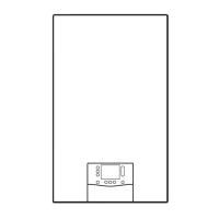
6.2 Product dimensions
Dimensions
A B C D
VUI 30/40
357 mm 580 mm 440 mm 720 mm
6.3 Installation site
This boiler is not suitable for outdoor installation. This boiler
may be installed in any room. However if the boiler is being
installed in a room containing a bath or shower it must only
be installed in zones 2 or 3. In GB this is the current I.E.E.
WIRING REGULATIONS and BUILDING REGULATIONS. In
IE reference should be made to the current edition of I.S.813
“Domestic Gas Installations” and the current ETCI rules.
If the boiler is to be installed in a timber frame building it
should be fitted in accordance with the current version of the
Institute of Gas Engineers document IGE/UP/7. If in doubt
seek advice from local building control.
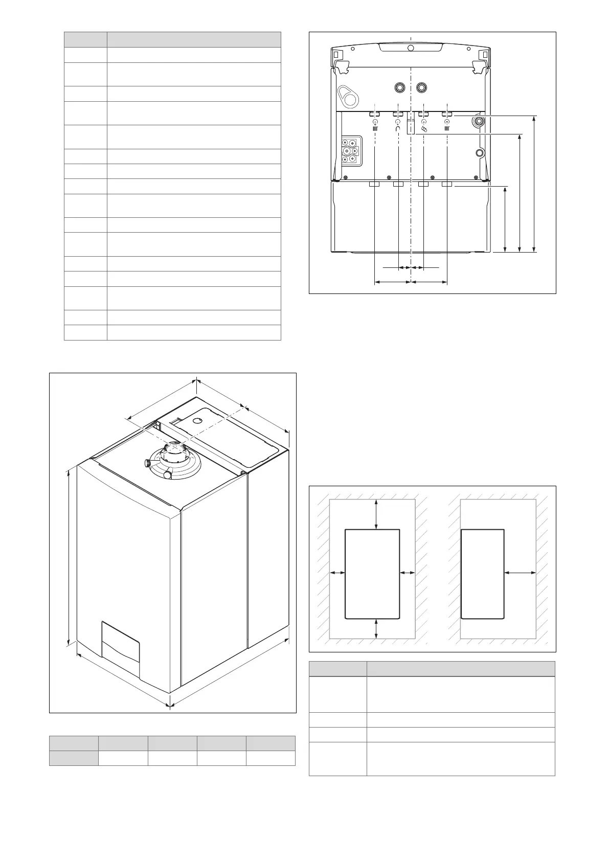
6.4 Minimum clearances
Minimum clearance
A 60/100 mm diameter air/flue pipe: 165 or
248 mm. → See mounting template
80/125 mm diameter air/flue pipe: 276 mm
B 180 mm
C 5 mm
D 500 mm in front of the heat generator to enable
easy access for maintenance work (may be
provided by an opening door)
 Loading...


