0020308121_04 Installation and maintenance instructions 39
23. Hinge the electronics box upwards.
24. Check the noted measured value against the manufac-
turer details.
Permissible gas flow pressure
Great
Britain
Natural gas H
1.3 to 2.3 kPa
(13.0 to
23.0 mbar)
Liquid gas P
2.3 to 4.3 kPa
(23.0 to
43.0 mbar)
Result 1:
Gas connection pressure/gas flow pressure in the per-
missible range
The product is ready to use.
▶ Install the front casing. (→ Section 7.11)
▶ Record the appliance gas inlet working pressure
(kPa resp. mbar) in the Benchmark gas boiler com-
missioning checklist.
Result 2:
Gas connection pressure/gas flow pressure not in the
permissible range
Caution.
Risk of material damage and oper-
ating faults caused by incorrect gas
connection pressure/gas flow pres-
sure.
If the gas connection pressure/gas flow
pressure lies outside the permissible
range, this can cause operating faults in
and damage to the product.
▶ Do not make any adjustments to the
product.
▶ Do not start up the product.
▶ If you are unable to eliminate the fault, contact the
gas supply company.
▶ Temporarily decommission the product.
(→ Section 14.2)
▶ Install the front casing. (→ Section 7.11)
▶ Close the gas stopcock.
▶ Disconnect the product from the power grid.
▶ You must not start up the boiler.
9.13.4 Checking the O₂ content
Note
Carry out the measurements only when the front
casing is installed.
Note
During a combustion analysis it is no longer a
requirement to check the CO₂ value as the CO₂
value is not required for the correct verification
of combustion. A standard-compliant check is
carried out via the O₂ value according BS 7967.
The O₂ value directly reflects the oxygen supply
required for complete combustion. It is still re-
quirement to record all combustion parameters
within the benchmark document.
1. Open the test opening at the flue gas analysis point.
2. Position the measuring probe for the flue gas analyser.
3. Start chimney sweep mode (→ Section 8.9).
4. Ensure that the heat load is correct.
– Max. DHW heat input (standard selection)
– Adjustable heat load (for some installations, this
deviates from the standard selection)
5. Wait until the product has completed the calibration via
S.093 and the status changes to S.004, S.014 oder
S.024.
6. Record the core current of the flue gas and wait until
the measured value has stabilised. Log the measured
value reading.
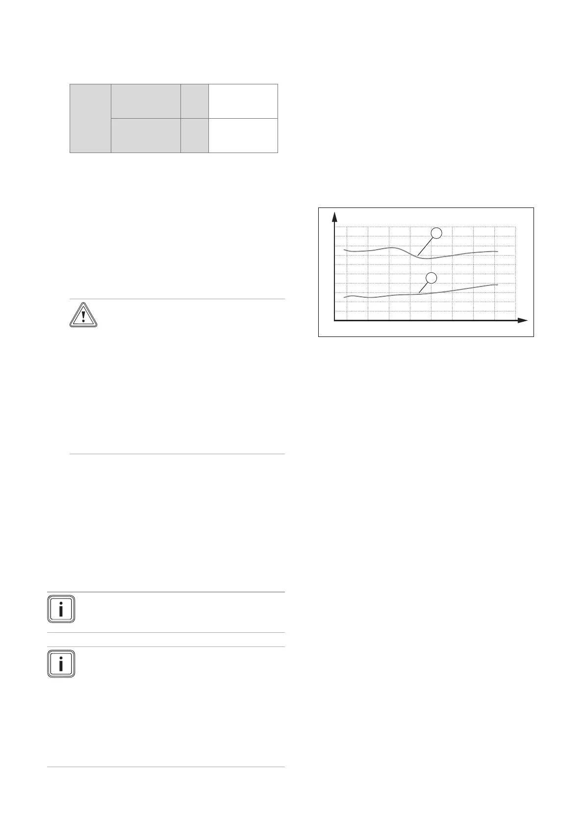
7. Compare the measured value reading with the per-
missible ranges from the diagrams.
5 1015 2025 30354045
B
4
6
8
10
2
0
A
2
2
1
A O₂ content [vol%]
1 Max. O₂ content,
natural gas
B Heat input [kW]
2 Min. O₂ content,
natural gas
Result:
The value lies outside of the permitted range
▶ Check the total pipe length of the air/flue system;
see the set-up instructions for the air/flue system.
▶ Check the air/flue system for recirculation and
blockages. (→ Section 9.13.2)
▶ Measure the O₂ content at the flue gas analysis
point again and log the measured value in the
benchmark log in the appendix.
▶ If the O₂ content remains outside of the permissible
range, correct the gas-air ratio via D.158 and meas-
ure the O₂ content again at the flue gas analysis
point.
▶ If the O₂ content remains outside of the per-
missible range, replace the control electrode
(→ Section 13.7.18) and reset D.158 to the factory
setting.
▶ Measure the O₂ content at the flue gas analysis
point again and log the measured value.
▶ If the value is still outside of the permissible range,
do not start up the product and, instead, report this
to customer service.
8. Remove the flue gas analyser and close the test open-
ing at the flue gas analysis point.
9.13.5 Checking the gas flow rate
The gas flow rate has been set during production and does
not require adjustment. With the front casing fitted check the
gas flow rate of the boiler as follows:
▶ Check whether the front casing (vacuum chamber) has
been closed tightly.
▶ Start up the product with the check programme P.01.
 Loading...


