0020308121_04 Installation and maintenance instructions 57
5. Pull the plug X12 out of the PCB.
6. Pull the free end of the line carefully through the grom-
mets on the heat generator and on the shift-load cylin-
der.
7. Detach the pump sensor line from the wiring harness
by pulling the plug out of the wiring harness.
8. Unscrew the pipe elbow
(6) from the housing.
9. Undo the screwed connection (2) on the connection
pipe (3).
10. Detach the spring clip (5) from the housing of the cylin-
der charging pump (4). At the same time, use your free
hand to support the cylinder charging pump to ensure
that it does not fall out of the housing.
11. Pull the cylinder charging pump downwards out of the
housing.
12. Install the pipe elbow on the new cylinder charging
pump and use new seals for it.
13. Install the new cylinder charging pump in reverse order
and use new seals.
14. Connect the pump's electrical wires in reverse order. In
doing so, pay attention to the correct pipe routing.
15. Reinstall the drain pipe (1) and use new seals.
16. Fill and purge the heat generator and the shift-load
cylinder.
13.7.12 Replacing the impeller sensor on the shift-
load cylinder
1. Close the domestic hot water system isolation valves
and drain the heat generator and shift-load cylinder on
the domestic hot water side.
2. Remove the drain pipe (1) from the expansion relief
valve on the heat generator.
3. Remove the plug from the impeller sensor.
4. Undo the screwed connections (2) and (3) on the angle
pieces (4) and (5).
5. Turn the impeller sensor slightly to the side and pull it
downwards to remove it from the housing.
6. Remove the pipe elbow from the impeller sensor.
7. Install the pipe elbow on the new impeller sensor and
use new seals for it.
8. Install the new impeller sensor in reverse order and
use new seals.
9. Connect the connection cable plug to the new impeller
sensor.
10. Reinstall the drain pipe (1) and use new seals.
11. Fill and purge the heat generator and the shift-load
cylinder.
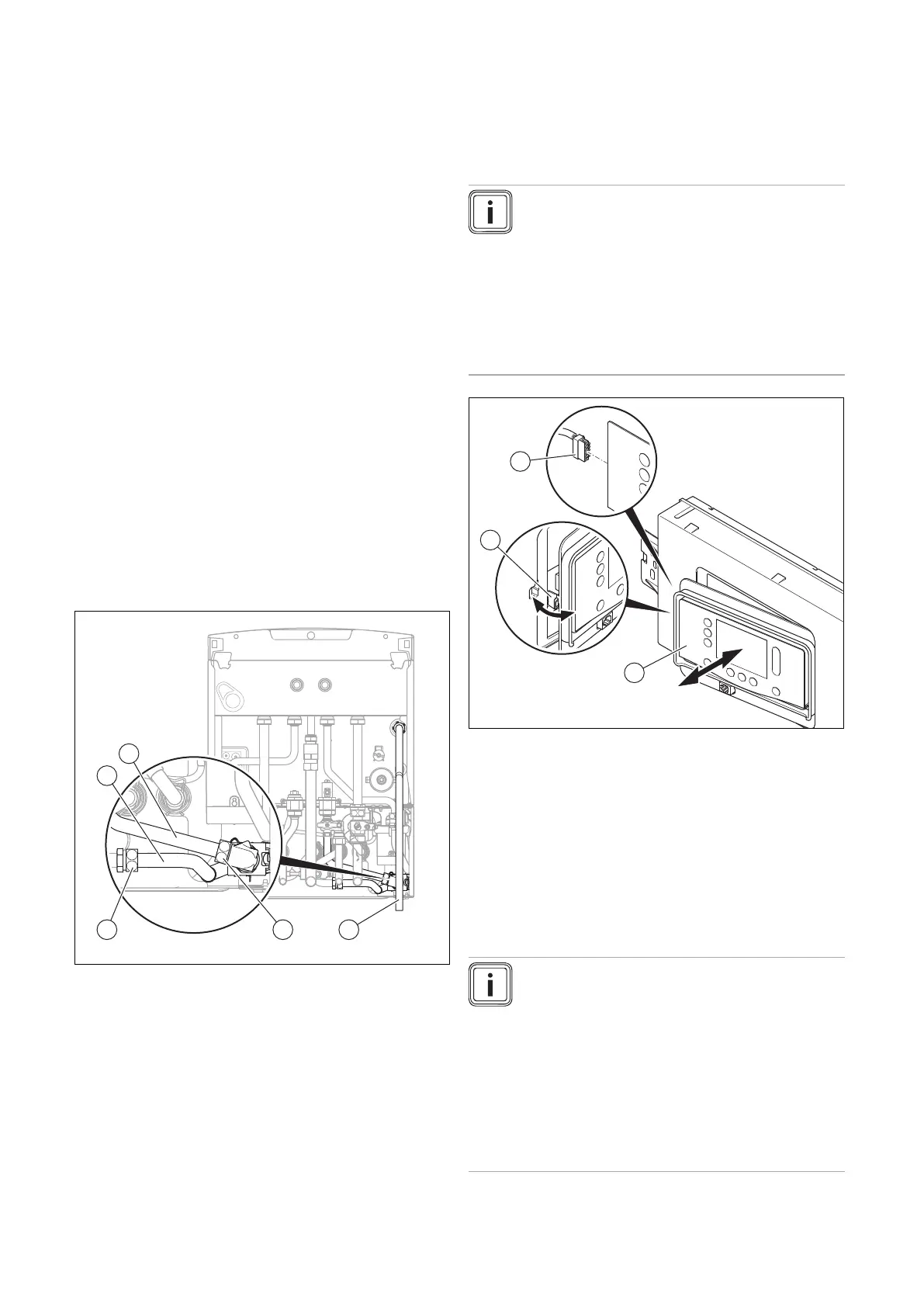
13.7.13 Replace the display
Note
Spare parts must only be used once.
If you only replace the display, when the product
is switched on, the new display adopts the para-
meters that were previously set from the PCB that
was not replaced. After replacing the display as-
sembly, the DSN code (Device Specific Number)
is transferred to the respective replaced assembly
and is written to its memory, where it cannot be
deleted.
1. Release the display (1) from the retainer (2) on the left-
hand side.
2. Remove the plug (3) from the display.
3. Replace the display.
4. Plug the plug into the new display.
5. Install the display in the retainer.
6. Establish the power supply.
◁ The DSN code is transferred from the PCB to the
display.
13.7.14 Replacing the PCB
Note
Spare parts must only be used once.
If fault F.064 is present, check diagnostics code
D.166 before you replace the PCB.
If you only replace the PCB, when the product is
switched on, the new PCB adopts the parameters
that were previously set from the display that was
not replaced. After replacing the PCB assembly,
the DSN code (Device Specific Number) is trans-
ferred to the respective replaced assembly and is
written to its memory, where it cannot be deleted.
 Loading...


