2.2. Sensor electronics
Sensor electronics of the FT model is shown in Fig. 3.
The sensor electronics board is installed between a
round cover and a base. The electronics contains a
microwave transmitter and receiver, and the electronics
for control, measurement and communciation.
When the electronics board is pressed on the base
plate, its snap-on connectors connect with the antenna
cable connectors on the base plate. Guide pins on the
base plate guide the connectors into position. The
temperature sensor, and the supply power and serial
communication lines from the TCU, are connected to
the connectors on the sensor electronics housing.
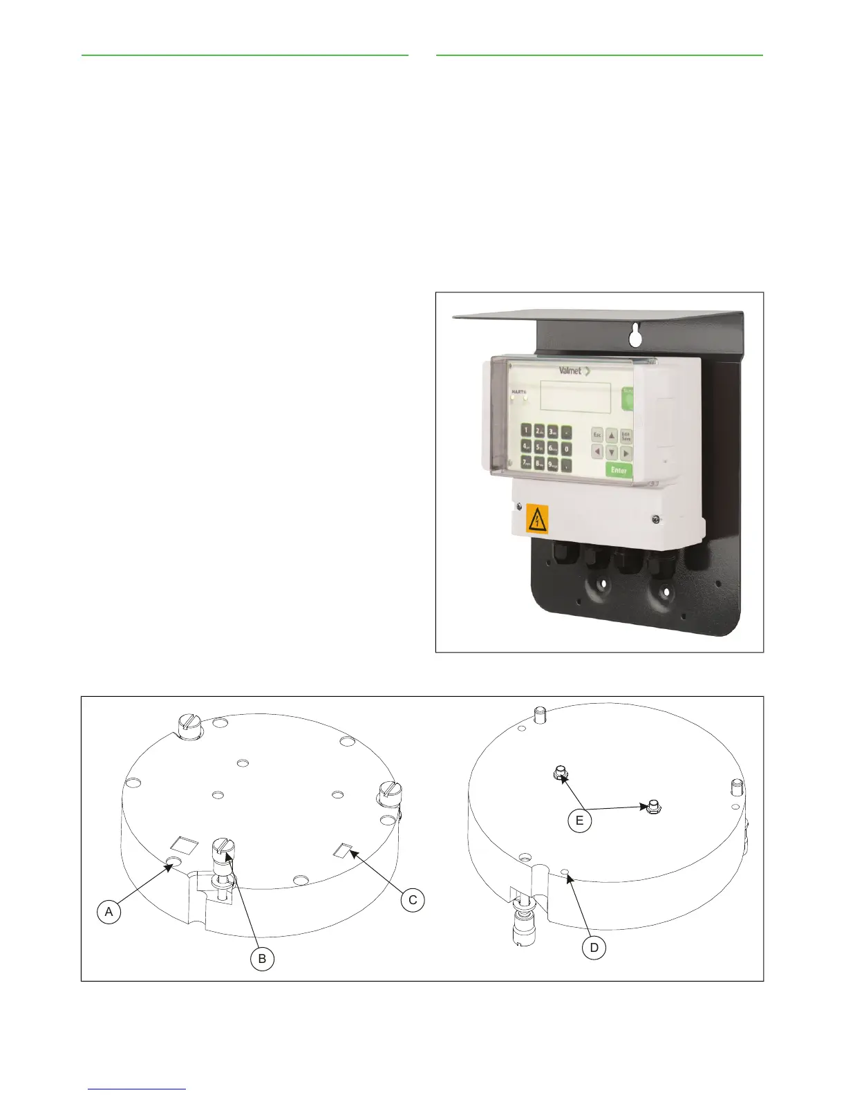
2.3. Transmitter Central Unit (TCU)
The TCU is the operating terminal and calculation unit
of the Valmet TS. It is operated by means of the keypad
and a four/line display. The TCU is delivered with a
shield attached to it (Fig. 2).
Connections:
– To sensor unit: operating voltage, RS485 serial
communication.
– To current outputs (2 passive outputs).
– To HART communicator (HART only in current out-
put 1).
– RS232 connection to a PC (for service purposes).
– Mains power.
Fig. 2. Operating unit, TCU.
Fig. 3. Sensor electronics: 1. power cable connector, 2. fastening screw, 3. temperature sensor connector, 4.
guide hole, 5. antenna cable connectors.
Installation & Owner's manual, OUL00489 V2.3 EN
10
Valmet Total Solids Transmitter