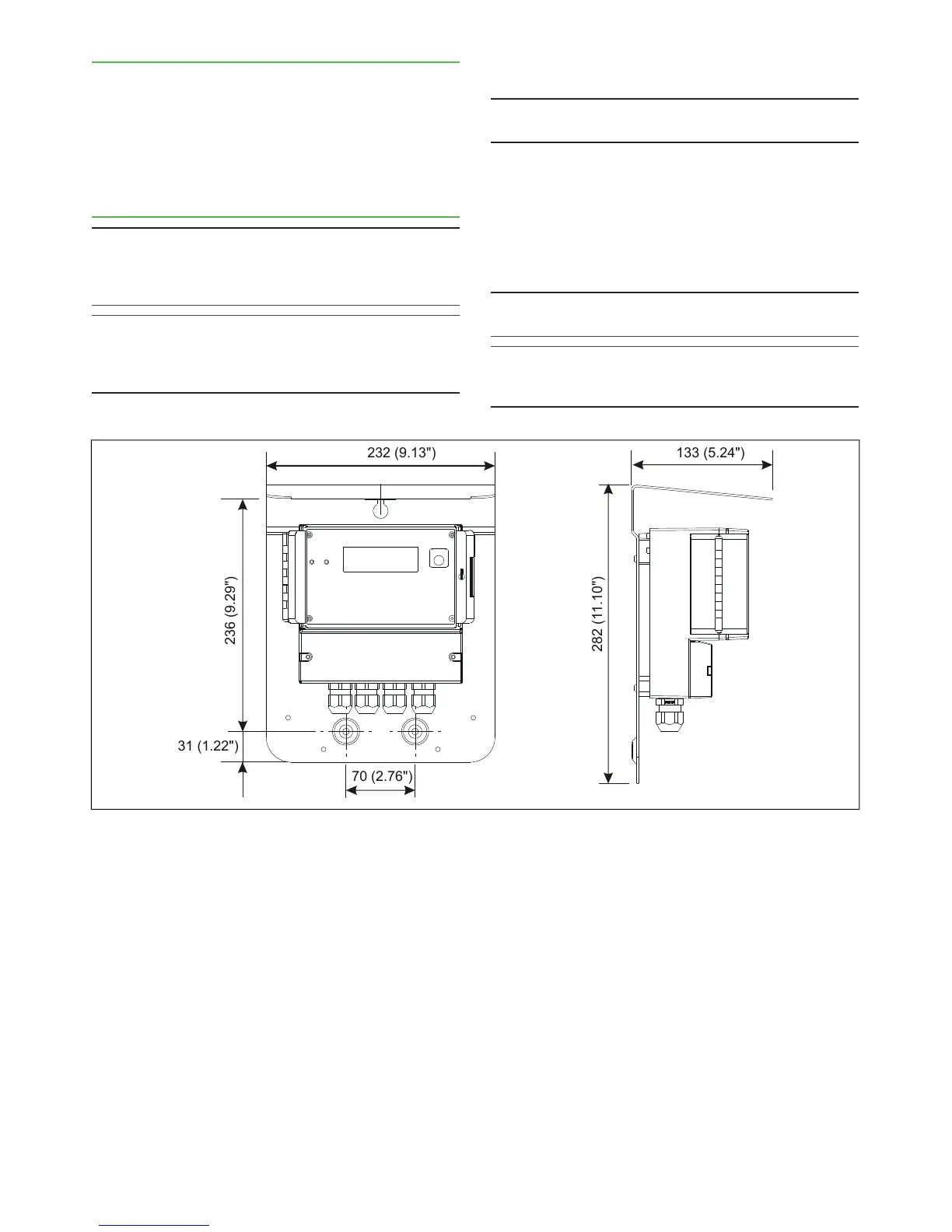
3.4. TCU and its shield
The TCU is delivered with a protective shield attached
to it. Choose an easily accessible location, and mount
the shield on the wall with three screws.
When choosing the TCU installation point, remember
that the sensor cable is 10 m (~ 33 ft) long The dimen-
sions of the shield are shown in Fig. 6.
3.5. Electric connections
NOTE: Before connecting the power supply wires, make
sure that the wires are not powered! Connect power to
the wires only after you have made and checked all
connections.
NOTE: If the TCU has been powered off for some time,
the display will take some time to light up. This delay is
perfectly normal, and the display will start working as
soon as its internal backup battery has recharged.
Sensor cable
NOTE: In normal deliveries the sensor cable is already
connected to TCU.
1. If the sensor cable is not connected, insert its open
end (= cable end without connector) into the TCU
connection box, and connect it as shown in Fig.
8.
2. Lead the other end of the sensor cable to the
sensor unit, and connect it to the connector on the
sensor electronics base plate.
NOTE: Do not put the sensor cable on the same rack with
power cables (motor/pump power cables etc.).
NOTE: Make sure that sensor power is switched off be-
fore opening the sensor cable connector shield or dis-
connecting the cable.