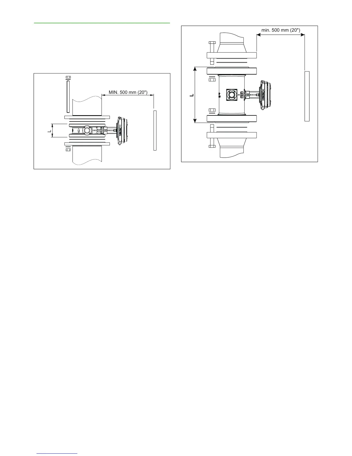
3.3. Installation dimensions
When installed, the sensor replaces a section of the
process pipeline (Fig. 4 and 5). The installation dimen-
sions are shown in the "Installation drawings" attached
to the end of this manual. A sticker on the electronics
housing indicates the correct installation direction in
relation to the flow in the pipeline.
Fig. 5. Valmet TS-FT PN100 installation principle.
Installation & Owner's manual, OUL00489 V2.3 EN
13
Valmet Total Solids Transmitter