Mains power
Connect the mains power cable (90 - 260 VAC) to TCU
through the left-hand conduit of the connector casing,
and connect it to the terminal strip as shown in Fig. 8.
Current signal cables
The TCU contains two current outputs. Current output
1 (CS+, CSIN) is hardwired to give the total solids
content signal. The user can choose either the process
temperature (°C/°F), process conductivity (mS/cm) or
solids content (TS% / g/l) to current output 2 (CS2+,
CSIN2).
Insert the current output cables to the TCU connector
casing through the inlets and connect them to the ter-
minal strip as shown in Fig. 8.
– Power supply wire to connector 'CS+' or 'CS2+'.
– Current output wire to connector 'CSIN' or 'CSIN2'.
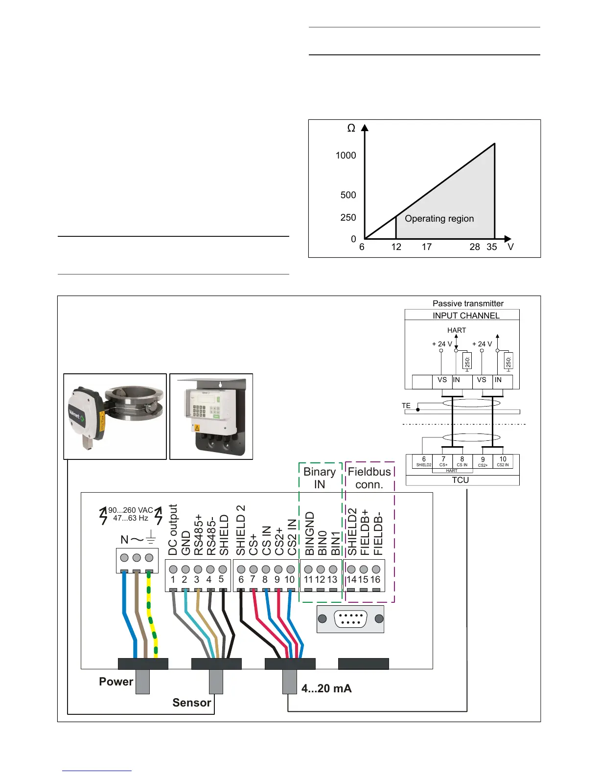
NOTE: The current output of the Valmet TS is a passive
output and it requires an external power source. The
minimum supply voltage is dependent on resistance.
NOTE: Do NOT connect the shield of the current output
cable at the TCU - connect it only at the mill system end!
Fig. 7 shows the resistance as a function of input
voltage. Resistance here means the total sum of all
resistances (measurement, cables, power supply) in
the current loop.
Fig. 8. Connections of the TCU.
Installation & Owner's manual, OUL00489 V2.3 EN
15
Valmet Total Solids Transmitter