VAMP Ltd Arc protection system
User manual
VAMP 220 / 220R
VM220.EN004 Vamp 24h support phone : +358 (0)40 573 6316
11
L>
I>
L>
I>
L>
L>
I>
I
L>
TR1
TR1
TR1
L>
I>
r
p
gna
ng
oc
agram
SW2
SW5
BIO option PCB
Power/Trafo/Trip PCB
from ARC sensor
from Slave
3 x
t
La>
80ms
100ms
150ms
Lb>
Ia>
&
Ib>
I>
L>
Tem p Al arm
L>
I>
LOC
LOC
La>
Lc>
L4>
TR4
TR4
I>
T5
T6
T6
T5
T5
T6
TR2
I>
LOC
L>
LOC
TRIP 2
TRIP 3
TempAl/TRIP4
TRIP 1
>1
L>
I>
>1
>1
T1
T2
T3
L
SW3
T3
LL
SW2
T2
L
SW1
T1
>1
SW7
SW8
int.sw.
&
&
&
+48V (BIO)
+5V (GND)
TRIP 6
TRIP 5
1
1
TR loc
TR loc
I>
L>
L
L
L
>1
1
2
3
4
5
6
7
8
9
10
11,12,13
14
15
16
17
18
L4>
0ms
>1
SW6
int.sw.
SW4
L
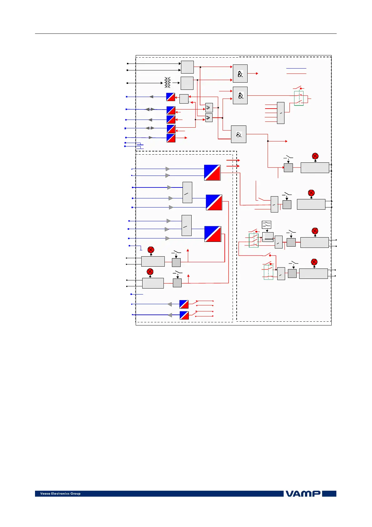
Figure 2.1.2-1 Trip signalling block diagram of VAMP 220.
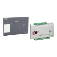
2.2. Slave unit VAM 12 CD
The slave units, which can be mounted into suitable places in
the switchgear compartments, serve as links between the
sensors and the master unit. Each slave unit can be connected
to ten arc sensors and one portable arc sensor. Up to 10 slave
units can be connected to one master unit. The master unit and
the slave units are interconnected by means of modular cables.
The slave units contain, for instance, the self-supervision of the
connected arc sensors.