VAMP Ltd Arc protection system
User manual
VAMP 220 / 220R
VM220.EN004 Vamp 24h support phone : +358 (0)40 573 6316
47
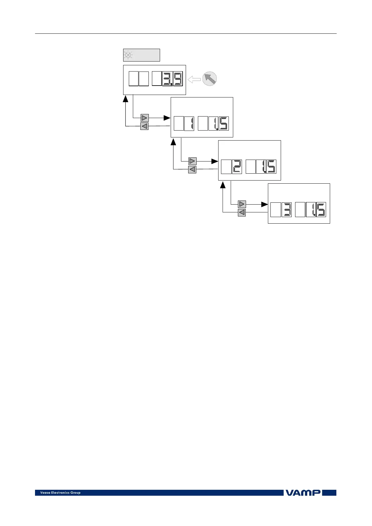
CURRENT
USE KNOB TO SET
THE START CURRENT
VALU E
CURRENT IN PHASE 1
CURRENT IN PHASE 2
CURRENT IN PHASE 3
Figure 6.5-2 Setting the start current and reading the actual measured
currents in the CURRENT mode.
The overcurrent subunit measures all three phase currents
(provided that all three phases are connected to the system,
which is recommended, see page 27) and starts if one of them
exceeds the set start current value. When the actual current in
one (or several) phases exceeds the level 0.8 x set value, the
display shows the warning code 200.
6.6. Relay output settings
The relay outputs are configurable from the dip switch on the
front panel of the master unit. See Figure 6.6-1.
Switches 1 to 4 determine the latching/non latching feature of
the corresponding trip relays. When a switch is turned on, latch
is on for the corresponding relay, which means that the relay
remains in drawn (conducting) state at an arc fault until is is
reset.
Switch 5 determines the function of trip relay 2. If switch 5 is
in ON position, trip relay 2 will function in parallel with trip
relay 1 and, in addition, trip on the BI/O trip signals from the
BIO option board (if installed). See the example in Figure 6.6-3.
If the switch is in OFF position, the trip relay 2 is exclusively
dedicated to BI/O trip signals from the BIO option board. See
Figure 2.1.2-1 and Figure 6.6-2.