VAMP Ltd Arc protection system
User manual
VAMP 220 / 220R
VM220.EN004 Vamp 24h support phone : +358 (0)40 573 6316
31
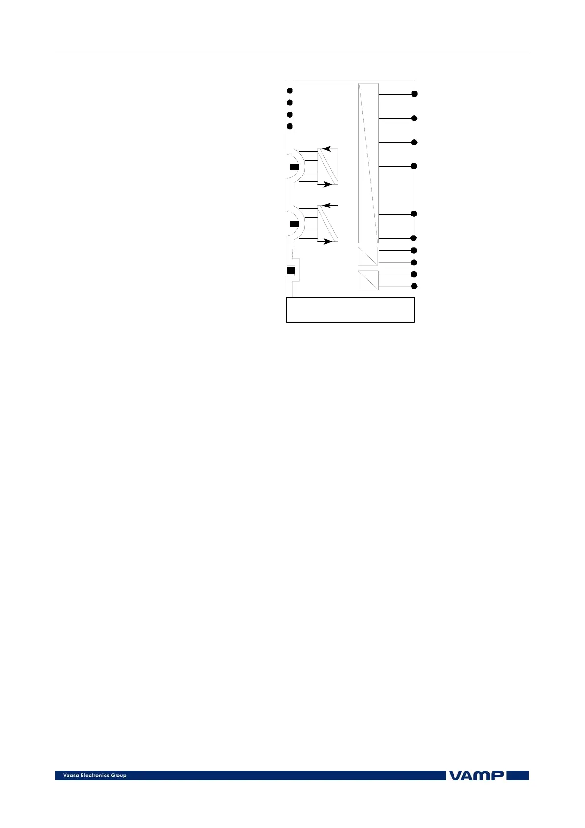
VAM 12 CD
1
2
10
.
.
.
TEMP
SSI
Serial link
24
0V
24
0V
COM 1
Serial communication
1 to the master unit
COM 2
Serial communication
2 to the master unit
Temperature sensor
input
Arc sensor
10 inputs
24V inputs from
the master unit
Portable sensor
input
Figure 5.4.3-1 Connections of the slave unit VAM 12 CD.
5.5. Installing sensors
5.5.1. Mounting arc sensor VA 1 DA
Mount the sensors in the switchgear cubicles in such a way
that the detecting surface covers the space to be supervised as
completely as possible. The sight must be free between the
sensor and the supervised area.
In open spaces (e.g. bus bar sections) there should be an arc
sensor approximately every 5 meters. Due to the wide detection
range of the sensors and the light reflection inside the
switchgear, the mounting position is not very critical.
The arc sensor can be mounted from the outside on a partition
wall of the switchgear. Fit the active part of the sensor into a
10 mm hole in the wall and fasten the sensor with one 4 mm
screw, see Figure 5.5.1-2.
The arc sensor can also be surface mounted on a wall using the
optional mounting plates VYX 01 or VYX 02.
NOTE!
The arc sensor must not be exposed to direct sun light or any
other strong light. Do not mount the arc sensor directly under a
light source.