VAMP 220 / 220R Arc protection system
User manual
VAMP Ltd
38
Vamp 24h support phone : +358 (0)40 573 6316
VM220.EN004
6. Commissioning
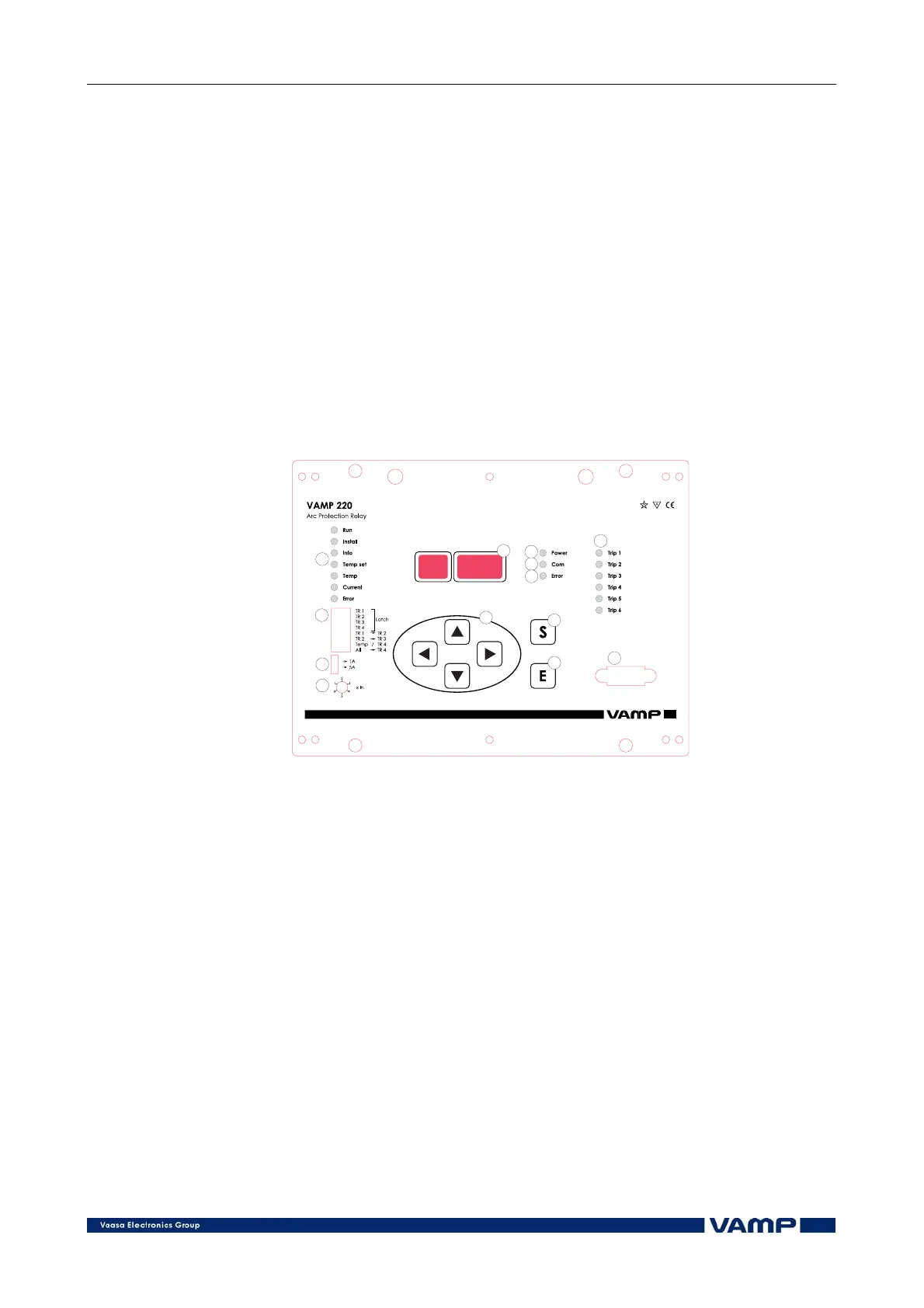
6.1. Using master unit control panel
6.1.1. General
The functions of the arc protection system can be supervised
and controlled by means of the control panel of the master unit.
The control panel has a number of indication leds, six flat push
buttons, a 5 digit 7-segment display, dip switches, a selector
switch and an outlet contact.
VY 056 A
1
2
3
4
5
6
7
8
9
10
11
12
13
Figure 6.1.1-1 The control panel of the master unit.
1. Push-buttons for choosing function
2. SET push-button for activating functions
3. ENTER push-button for executing functions
4. Display
5. POWER LED, indicates that all the supply voltages of the
system are in order
6. COM LED, indicates that serial communication is going on
7. ERROR LED, indicates that an internal fault has been
detected in the master unit
8. Mode indicator LEDs
9. Switch selector for setting the rated current of the
overcurrent unit
10. Setting knob for setting the start current of the overcurrent
unit. Separate setting knob for E/F setting (220R)
11. Dip switches for setting trip relay matrix
12. Trip indicators