VAMP 220 / 220R Arc protection system
User manual
VAMP Ltd
36
Vamp 24h support phone : +358 (0)40 573 6316
VM220.EN004
X2
X3
X1
X6
X2
X3
X1
X6
1
2
3
4
5
6
7
8
9
10
11
12
13
14
15
16
17
18
1
2
3
4
5
6
8
9
10
11
14
15
16
17
18
1
2
3
4
5
6
7
8
9
10
11
12
13
14
15
16
17
18
19
20
1
2
3
4
5
6
7
8
9
10
11
12
13
14
15
16
17
18
1
2
3
4
5
6
8
9
10
11
14
15
16
17
18
La> BIO
1
2
3
4
5
6
7
8
9
10
11
12
13
14
15
16
17
18
1
2
3
4
5
6
8
9
10
11
14
15
16
17
18
1
2
3
4
5
6
7
8
9
10
11
12
13
14
15
16
17
18
19
20
1
2
3
4
5
6
7
8
9
10
11
12
13
14
15
16
17
18
1
2
3
4
5
6
8
9
10
11
14
15
16
17
18
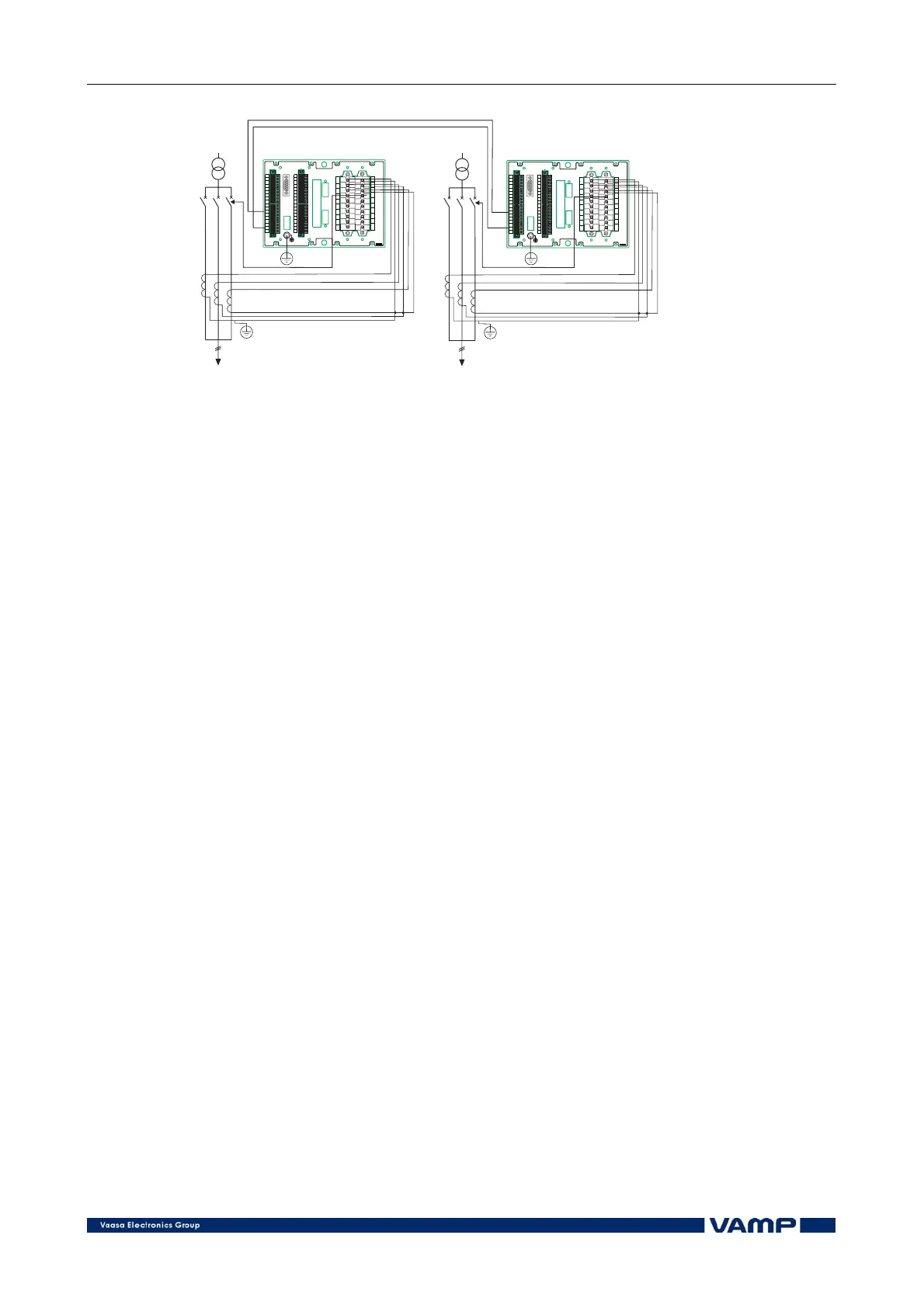
Figure 5.7-1 Arc protection system with two master units (example).
5.8. Wiring systems with selective arc
protection
Wire the system as follows:
• Connect the arc sensors of one certain zone in normal way
to the slave units.
• Connect each slave unit to a master unit belonging to the
zone.
• Connect the bidirectional arc information La via the BI/O
bus (terminal X3-12,17) to all master units in that zone.
The unidirectional arc information (terminals X3-14,17, Lc>)
can be fed from the master unit (terminals X3-12,17, La>) of
the next zone. By doing so, the system will trip also the circuit
breakers which feed the next zone. See Figure 2.7-1.
5.9. Checking wirings
Check the secondary wiring by visual inspection and, when
needed, by measuring, to eliminate possible incorrect wirings,
which may cause malfunction of the system or associated
devices.
5.9.1. Visual inspection
Perform a visual inspection of the wiring. Especially check the
wire bunches for adequate slack where needed over hinges.
Check the screw terminals for correct tightness.
Check, that no wire strands are protruding from the terminals.