VAMP 220 / 220R Arc protection system
User manual
VAMP Ltd
48
Vamp 24h support phone : +358 (0)40 573 6316
VM220.EN004
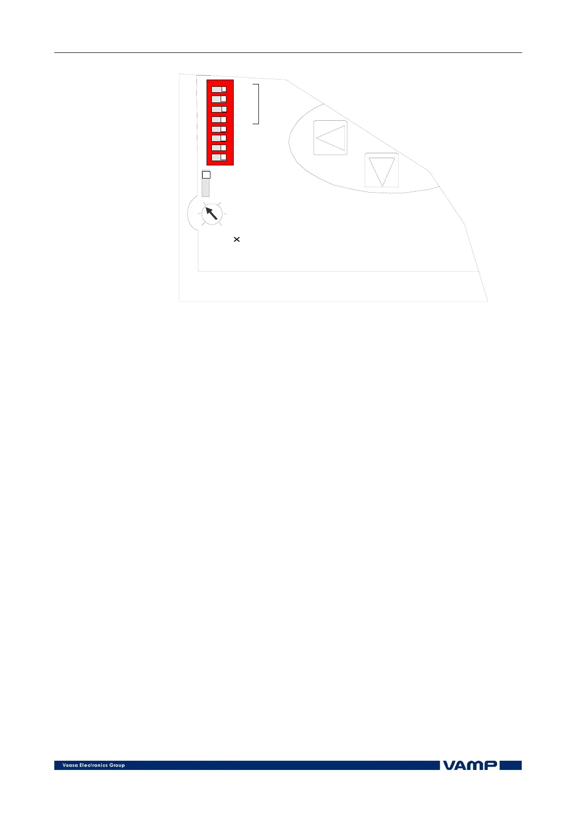
-> 1A
-> 5A
1...6 In
TR1
TR2
TR3
TR4
TR1 -> TR2
TR1 -> TR3
Temp / TR4
All / TR4
Latch
1
2
3
4
5
6
7
8
off o
Figure 6.6-1 The DIP switches on the front panel of the master unit.
Switch 6 defines the function of trip relay 3. If switch 6 is in
OFF position, the trip relay 3 will function in parallel with trip
relay 1. However, only local overcurrent and ARC signals will
activate this stage (no BI/O lines).
If the switch is ON, trip relay 3 will funcion as an CBFP relay
to trip relay 1. The possible time delay settings are fast, 80, 100
or 150 ms. These must be specified when ordering. See the
example in Figure 6.6-4.
Switches 7 and 8 determine the function of trip relay 4.
When switch 7 is turned ON, and switch 8 OFF, relay 4
becomes a trip relay which is tripping on any OC signal if a
dedicated arc BIO line (Lc>) is activated (see also the function
of switch 8). See Figure 6.6-5.
To use relay 4 for external temperature alarm, set switch 7 in
OFF position.
If switch 7 and 8 both are turned ON, all trip signals will be
routed to trip relay 4, which means that relay 4 will trip if one
or more of the trip relays 1 ... 3 trip. See Figure 6.6-6.